Exercise 1: building a two-way conveyor system – FlexLink Configura User Manual
Page 30
Exercise 1: Building a Two-Way Conveyor System
In this exercise we will build a simple two-way system, change system length, add
supports and guide rails, render a 3D image and print a quotation.
Before creating a professional printout of your quotation, including a drawing and a 3D-
rendered image of your system, you will learn how to customize the layout to suit your
particular needs.
-----------------------------------------------------------------------------------------------------
Proceed as follows:
1. Start Configura by selecting Programs/Configura for FlexLink/Flex in your MS
Windows Start menu or simply by clicking on the Flex icon on your desktop.
2. Go to the File menu and select Control Panel. Make the desired language and unit
settings and activate Auto save by checking that box.
3. In the File menu, select Save as to name the file from the start and to determine
where to save it.
4. Make sure that the first component tab, Customized Conveyor, is selected. Do your
pre-sets and select the Drive Unit component. Move the component onto the drawing
area and click. Enter the desired angle by and click again. Now you will be presented
with yet another choice; Right: Yes/No. By moving your mouse in the desired
direction, you can select the motor position before finally clicking the drive unit in
place.
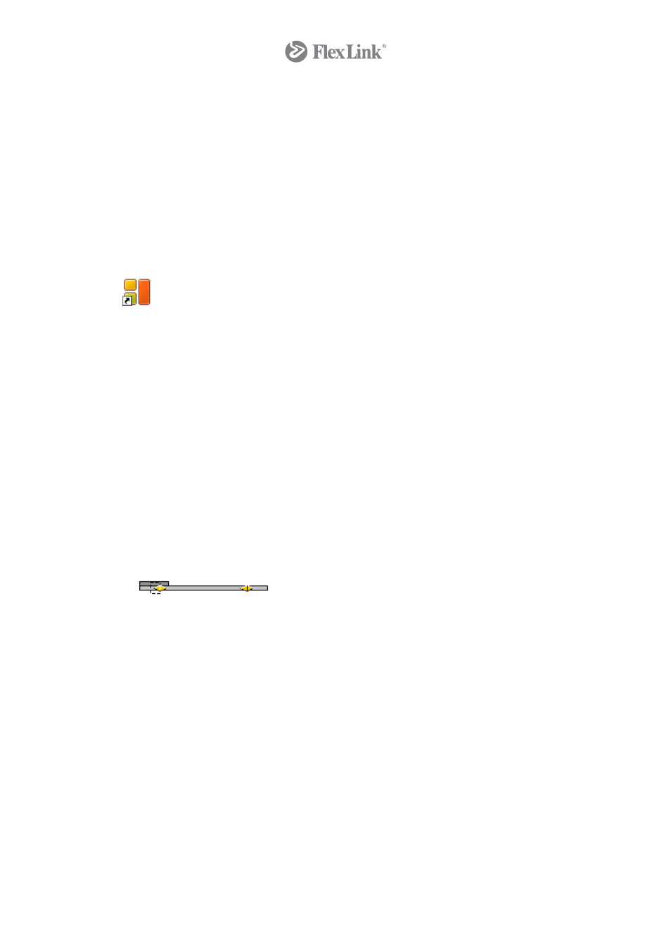
5. Select the Beam, snap it to the drive unit and click. Enter the desired length and
confirm by clicking.
6. Up until now, the color of your system has been red, indicating that it is not a
complete system. To make it valid, you have to finish off with the Idler. Select the
idler, snap it to the beam and click. Your system now turns gray, indicating that it is a
valid two-way system including a drive unit and an idler.
7. You can change the length of your conveyor system at this stage by right clicking on
the beam and selecting Settings. Select Beam and enter your preferred system
length in the Length field (always the length of the center line between two break
points), e.g. 5000 (mm). Click OK. Your system is now 5000 mm in length.
8. Before proceeding to supports and guide rails, have a look at your conveyor system in
its current state by clicking on one of the camera icons, Auto 3D (Fast) or Auto 3D
(detailed), in the toolbar. Close the 3D rendering window to return to your drawing.
9. Under the Support heading, click on the Settings button to do your pre-sets. Then
select the Auto Support component and snap it to the conveyor. Click once to
automatically add the required support modules to your system. Render an image to
view the result.
10. In order to change the type of support module, right-click on the beam and select
Remove all supports. Go back to the component tab, change the settings and add
the new support to the system.
11. Under the Guide Rail heading, click on the Settings button to do your pre-sets.
Select the Auto Guide Rail component and snap it to the conveyor. Click once to
30
© Copyright Configura Sverige AB 2004. All rights reserved. Reproduction, copying or distribution to a third party is prohibited unless
consent in writing has been given by the owner.