50 chapter 4 – menu system diagnostics – Datamax-O'Neil E-Class Mark III Operator’s Manual User Manual
Page 56
50
Chapter 4 – Menu System
Diagnostics
The Diagnostics menu contains testing functions and printhead reporting selections:
Hex Dump Mode*
Options Testing*
Print Test Rate (min)*
Sensor Readings*
Ribbon Sensor Limits*
Flash Module Report*
Items denoted with an asterisk (*) are only accessible through the Advanced Menu.
The menu selections are defined as follows:
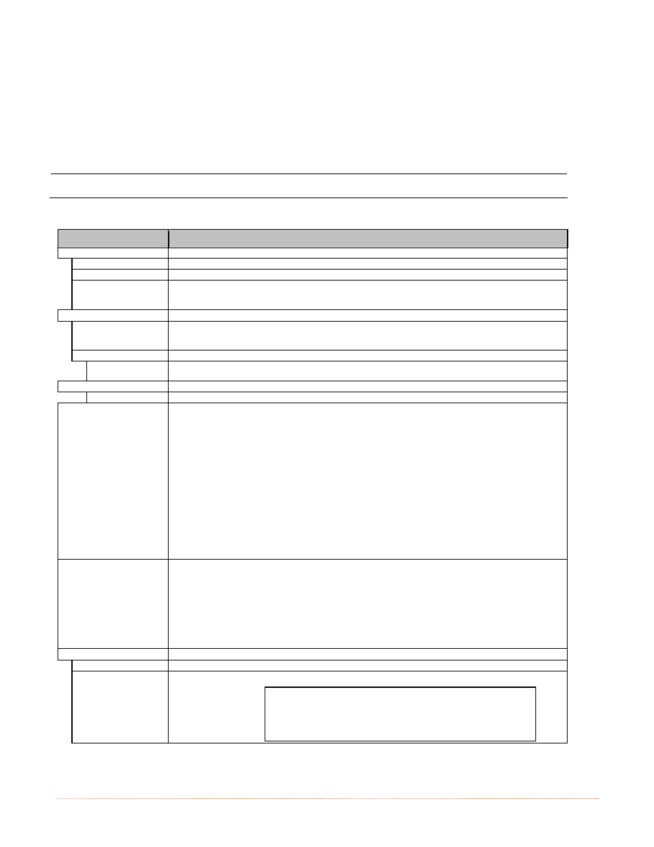
DISPLAYED ITEM
ITEM DESCRIPTION
HEX DUMP MODE
Determines how the printer handles the data received from a host, where:
ENABLE
The printer outputs the raw ASCII data it receives without interpretation; no processing occurs.
DISABLE
Processes data normally. (Default Setting)
FILE CAPTURE
Saves the incoming data to Module H (USB thumbdrive) if present; otherwise, the file is stored on
Module G. The file name, in the form [dmx_xxx_yyy.dpl], where the count is automatically
incremented for every capture and a unique printer time stamp (xxx), is assigned.
OPTIONS TESTING
Performs printer option diagnostics or monitors and outputs test results, where:
TEST PRESENT
SENSOR
Performs a functional test of the Present Sensor by indicating LABEL PRESENTED (when a label
blocks the sensor) and LABEL NOT PRESENTED (when no label blocks the sensor). (Note that this
test can also be used to check the sensor function of the Peel & Present option.)
TEST CUTTER
Performs a functional test of the Cutter, where:
PERFORM TEST
001 TIMES
Cycles the cutter blade a selected number of times (0 - 999), with PASS / FAIL results given for
each cycling attempt.
PRINT TEST RATE (MIN)
Sets a label-to-label delay interval (0 - 120 minutes) when Test label batch printing, where:
000
Is the Default Setting.
SENSOR READINGS
Displays the values (0 – 255) from the printer sensors, where:
THR TRAN
RIBM
24V
103 091 009 171
PS HD RANK
003 255 050
THR = Printhead thermistor sensor;
TRAN = Gap media sensor (REFL when set to reflective);
RIBM = Ribbon sensor;
24V = 24 volt power supply sensor;
PS = Present sensor;
HD = Printhead position sensor; and,
RANK = Printhead ranking resistor.
RIBBON SENSOR LIMITS
Displays the values from the ribbon sensor readings (see example below) for printers equipped with
the thermal transfer option, where:
RIBBON ADC LOW
111
RIBBON ADC HIGH
249
FLASH MODULE REPORT
Displays the module report data, where:
VIEW
Displays the data.
Prints a reference label:
FLASH MODULE REPORT
SUN 12:44PM 23MAY2011
Module G Mount Fail: 0
Module G Reformatted: 0