4chapter 2 – printer setup, 2 interface connections, Cable requirements – Datamax-O'Neil E-Class Mark III Operator’s Manual User Manual
Page 10
4
Chapter 2 – Printer Setup
2.2.2 Interface Connections
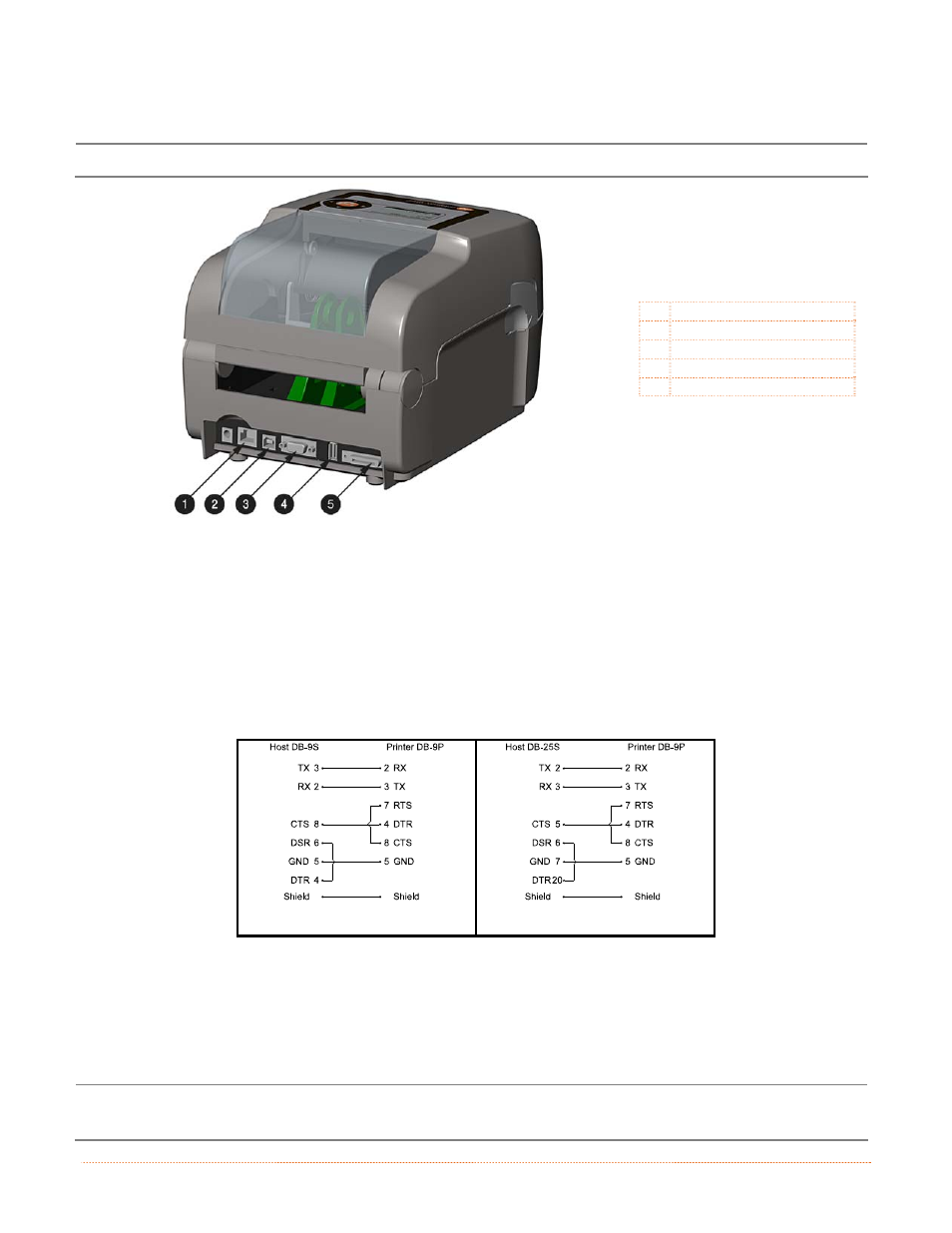
Before connecting interface cables to the printer, ensure that the Power Switch is in the OFF (O) position.
312
Ethernet Port
USB Port
Serial Port
USB Host Port
Parallel Port
Cable Requirements
Choose the correct cable when interfacing the printer to the host:
The Parallel Port (optional) supports parallel communications via a 36-pin male mini-Centronics
connector. Bi-directional communications (forward and reverse channels) is supported when an IEEE
1284 compliant cable and supporting host software is used.
The Ethernet Port supports Wired LAN communications (see Appendix B for information).
The Serial Port supports RS-232C communications via a DB-9 connector with specific pin-outs
(interface cable part numbers and pin-outs are given below; contact your reseller to order). Serial port
settings are menu-selectable and must match the host settings.
Part # 32-2483-01
Part # 32-2301-01
The USB Port supports high-speed serial communications and requires a standard USB interface
cable.
The USB Host Port (optional). The USB Host Port allows the printer to accept external USB memory
devices for storing graphics, label formats, fonts, and firmware. The port can also accept an USB
keyboard for standalone, direct data (Line mode) input applications; see the Programmer’s Manual for
more information on how to utilize the port.
The printer automatically establishes communications with the first port through which valid data is
received. Afterward, a timeout period must be exceeded (or power must be cycled OFF and ON) to change
the established communications port.