Installation, Electrical connection, Installation 12 – BEI Sensors MHK5 Absolute Hollow Shaft Encoder User Manual
Page 12: Device net user manual
DEVICE NET USER MANUAL
BEI IDEACOD SAS
Espace Européen de l’Entreprise
9, rue de Copenhague
B.P. 70044 Schiltigheim
F 67013 Strasbourg Cedex
Tél
: +33 (0)3 88 20 80 80
Fax : +33 (0)3 88 20 87 87
Mail :
Web : www.bei-ideacod.com
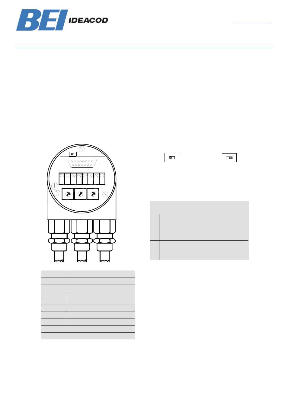
6. Installation
6.1. Electrical connection
Last Device
Device X
The rotary encoder is connected by three
cables. The power supply is achieved with a
two-wire connection cable through one PG 9.
Each one of the twisted-pair and shielded bus
lines are guided in and out through two PG 9
on the right side (as seen on clamps)
ON
T
R
T
ON
R
There is a resistor provided in the connection
cap, which must be used as a line termination
on the last device
Resistor:
The setting of the node number is achieved by
2 turn-switches in the connection cap. Possible
addresses lie between 0 and 63 whereby
every address can only be used once. 2 LEDs
on the backside of the connection cap show
the operating status of the encoder.
Clamp
Description
Ground
+
24 V Supply voltage
-
0 V Supply voltage
CG
CAN Ground
CL
CAN Low
CH
CAN High
CG
CAN Ground
CL
CAN Low
CH
CAN High
DeviceNet Devices
BCD coded rotary switches
x1
x10
Device adress 0...63
Setting CAN-node number
xBd
Setting of the baud-rate
G
H
-
+
G L
L
H
ON
0
9
8
7
6
5
4
3
2
1
7
8
2
56
4
3
0
9
1
x10
x1
8
7
2
6
5
4
3
0
9
1
Bd
RT
Page 12
UME-OCD-D2
Version 05/04