Stainless steel strainer option, Operation instructions, Control switch – ClimaCool UGW Manual User Manual
Page 58: Water resistance, Pressure differential alarm package option
www.climacoolcorp.com
56
Operation Instructions
Flush valve line must be piped to atmospheric pressure such
as an open floor drain. The flush line should not undergo
any changes in elevation and should be sloped downward in
the direction of drainage . Do not pipe the flush or drain line
into a pressurized line.
Note: The Automatic Timer Flush Package needs to be
programmed when it is received by the end-user. The
programming is simple and takes only a few moments.
However, because every application has different
parameters that affect the required frequency between
flushes and the duration of the flush, the end-user must
choose the controller’s settings (refer to specific strainer
type manual).
To Program the ATF Controller
1. Plug the transformer into a 120-VAC outlet .
2. Insert the 12-VDC plug coming from the transformer
into the jack on the underside of the ATF box .
3. Test for power by pressing the manual flush side of the
control switch (lower switch light should come on then
the valve will start to open) .
4. Adjust the “ON TIME” (Valve Open) by turning the
inner timer ring with the GREEN POINTER clockwise to
increase duration . The ON TIME RANGE is factory set at
eight seconds. (See Figure 22).
5. Adjust the “OFF TIME” (Valve Close) by turning the
outer ring with the RED POINTER clockwise to increase
duration . The OFF TIME RANGE is factory set at twenty-
four (24) hours. (See Figure 22).
6. Set the control switch to auto flush. The red off light
on the timer will come on and the upper light on the
switch will come on and stay on. During the flush cycle
the on light on the timer and the lower switch light
will come on .
Control Switch
Control switch flushing is initiated by pressing and holding
down the manual control switch located on the front of the
controller (See Figure 23). The manual flush control switch
can also be used to conveniently drain the water out of the
strainer before removing the conical screen element from
the strainer housing . A yellow indicator arrow on top of
the ATF valve will rotate in sync with the ball valve to show
the valve position (open or closed). When the manual flush
control switch is released, the valve will automatically close .
SAFETY FIRST! - Keep fingers away from valve opening
to avoid getting caught in the moving parts. The electric
motor supplied a sufficient amount of power to cause
personal injury. Take precaution when handling.
Water Resistance
The valve and controller are water-resistant, but not
water-proof . Do not install below ground level where the
component can be submerged in water . Only remove
the cover plate from the valve controller when setting or
changing the flush settings. Keep the cover tightly sealed on
the unit during normal operation .
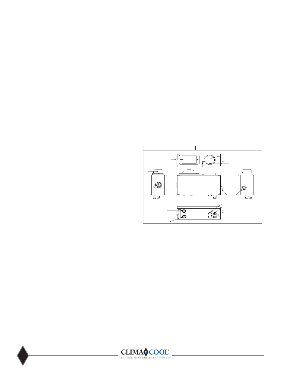
Pressure Differential Alarm Package Option
The pressure differential alarm (PDA) option continually
monitors and displays the strainer’s inlet and outlet
differential pressure. When the strainer element (conical
strainer basket) becomes significantly clogged, the pressure
differential switch-gauge will trigger an audible siren and
a visual flashing alarm light. These alarms are intended to
alert maintenance personnel that the strainer element
must be removed and cleaned (See Strainer Element
Cleaning on page 54) .
Figure 25
PSID High
PSID Low
Pressure Differential Alarm (PDA) option
Alarm Reset Button
FRONT
VIEW
LEFT SIDE
VIEW
Power To ATF
110 Volt/12 Volt DC
Wall Transformer
Visual
Alarm
Audible
Alarm
Pressure Differential
Switch-Gauge
LED Power Indicator
Differential
Set-Point Contact
Cover-Plate Screw (4) in Corners of
Box (DO NOT REMOVE).
Visual
Alarm
RIGHT SIDE
VIEW
TOP
VIEW
BOTTOM
VIEW
AUX Contacts
(On or Off with Alarm)
Red & Black
Cable Retainer
Operation Instructions
Remove the power supply and insert the connector end into
the socket on the bottom of the PDA housing (See Figure
25 above) and plug the transformer into the power source .
Standard systems are supplied with a 120V power supply to
the primary of the transformer, with an output secondary of
12 VDC. The pressure differential switch-gauge is factory set
to 7-8 psi. The CS strainer operates at a pressure differential
slightly less than 1 psi during maximum flow when the
strainer screen is clean. By the time the differential pressure
reaches 7-8 psi, the strainer element will be significantly
clogged and require immediate removal and cleaning . To
adjust the pressure differential switch-gauge setting, insert
a 1/16” allen wrench and rotate the differential set point
contact to the desired location (See Figure 25). Note: It is
not recommended to set the differential switch-gauge
higher than 10 psi. Disabling the alarm or increasing the
alarm set point could result in damage to the strainer
element and allow debris to pass into the system.
Stainless Steel Strainer Option