Electrical connection – ClimaCool UGW Manual User Manual
Page 21
19
www.climacoolcorp.com
Electrical Connection
The power for all modules is taken from a suitable circuit
breaker/fused disconnect power supply within the main
panel . The electrical service enters the individual modules
through the top into the module’s control panel enclosure .
Proper grounding of the module is mandatory . Before
carrying out any electrical work, confirm that the main
supply is isolated. A typical power wiring is located on page
60 – Power Distribution Drawing . Knockout drawings are
provided . Do not drill into cabinet; shavings can damage
electronic components . The power for all individual modules
shall be in compliance with all local and national codes .
CoolLogic Control System Wiring
A separate 115 volt power supply is required to power the
CoolLogic Master Control Panel . Communication between
the Master Control Panel and chiller modules requires a
simple two-conductor 18 AWG shielded cable rated at 60°C
minimum, daisy chain connection . Control wiring cannot be
installed in the same conduit as line voltage wiring or with
wires that switch highly inductive loads such as contactor
and relay coils. Refer to the Power Distribution schematic
on page 60 of this manual for more information . All wiring
shall be in compliance with all local and national codes .
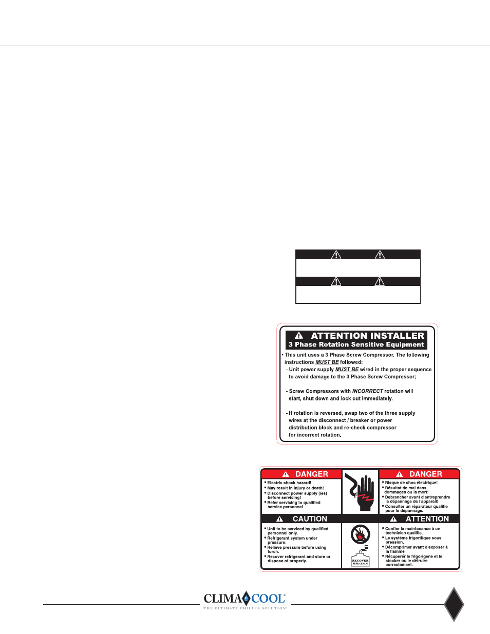
Electrical Phase Sequencing
Proper clockwise rotation for scroll compressor motors
is important to prevent damage to the compressors .
ClimaCool recommends the use of a phase sequence
indicating instrument following the manufactures
directions . An alternative is to “bump test” the compressors
one at a time with pressure gauges attached to the high and
low gauge ports of the compressors to check for proper
rotation . Energize the compressor for a few seconds to
ensure the discharge pressure gauge increases significantly.
If the discharge pressure does not increase, proper
rotation is reversed . Compressor rotation can be reversed
by opening the main electrical disconnect and switching
any two of the main power supply leads feeding that
compressor’s contactor .
Proper Voltage Balance
Occasionally, in three phase circuits, a voltage imbalance
occurs between phases . It is not recommended to operate
equipment when an imbalance greater that 2% occurs . This
causes motors to run at high temperatures and may affect
their longevity . The following example describes how to
calculate the average voltage of the three phases to see if
the imbalance is greater than 2% .
Example: Line 1 = 226v Line 2 = 230v Line 3 = 228v
The average is: (226+230+228) / 3 = 228v
Next, [100(228-226)] / 228 = 0.9%
The voltage imbalance of the three phase circuit is 0 .9% .
This is well under the 2% range .
Voltage/Phase Monitor
Voltage/phase monitors are factory supplied for field
installation with the CoolLogic Master Control Panel . The
voltage/phase monitor helps guard the chiller bank against
voltage fluctuations, phase failure or phase reversal
conditions which could void your warranty . The voltage/
phase monitor has three wires that connect to the main
three phase power chiller bank input . Two low voltage
control wires are connected to the CoolLogic Master Control
Panel . Do not install control wiring in the same conduit
as line voltage wiring or with wires that switch highly
inductive loads such as contactor and relay coils . Note: It
is mandatory to install one (1) monitor per bank at main
power distribution panel to monitor voltage and phasing of
power to the modules. See Wiring Diagram on page 20.
WARNING!
WARNING! To avoid possible injury or death due to electrical
shock, open the power supply disconnect switch and secure it
in an open position during installation .
CAUTION!
CAUTION! Use only copper conductors for field installed
electrical wiring . Unit terminals are not designed to accept
other types of conductors .