Water piping configuration – ClimaCool UGW Manual User Manual
Page 14
www.climacoolcorp.com
12
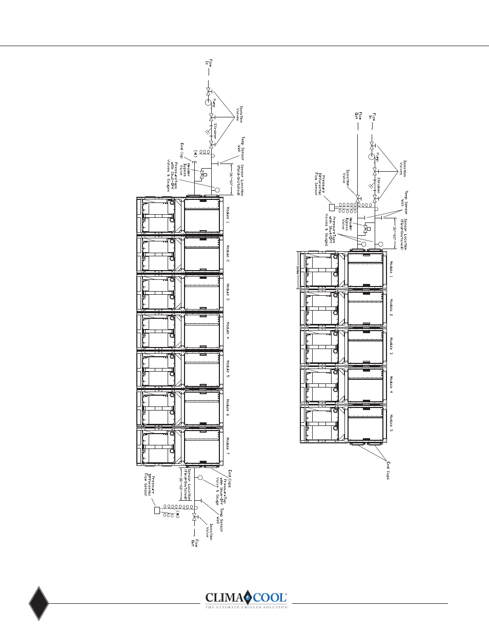
Water Piping Configuration
Notes:
1 .
Figures 9 and 10 are required piping for proper water regulation and distr
ibution through ClimaCool modular chillers
.
2.
Module order and incoming/outgoing water flow as shown in both Figure
9 and 10 can be set up as either a left-to-right or right-to-left configuration.
3.
Evaporator Hydronic Circuit shown. Piping configurations are similar for t
he condeneser water hydronic circuit.
4.
For condenser and chilled water (evaporator) inlet/outlet location dimens
ions, refer to page 6 Module Dimension Data.
5.
A pressure differential flow sensor is a required safety device for ClimaCoo
l modular chillers on the chilled and condenser water circuits.
6 .
A strainer with a minimum of 60 mesh stainless steel screen is a required
safety to protect the brazed plate heat exchangers on both chilled and condenser water sides of the system
.
7.
Maximum water flow rates for both evaporator and condenser water hea
der systems in one bank of modules is 2,400 gpm
.
8 . Bypass is
mandatory
for systems utilizing motorized valves
.
9 . Header bypass valve may be installed at either end of bank
.
10. For over seven (7) modules, please consult the factory.
Figure 9 - Field Piping Direct Return
Figure 10 - Field Piping Reverse Return