Pre-startup – ClimaCool UGW Manual User Manual
Page 23
21
www.climacoolcorp.com
Pre-Startup
All startups must be performed by ClimaCool factory
trained personnel. Prior to chiller startup, there are certain
essential checks which must be completed . Failure to carry
out these checks could result in damage to the chiller
voiding the modules warranty .
Electrical
It is imperative to turn off the main electrical power supply
and follow proper lock-out/tag-out procedures prior to
servicing any of the chiller’s electrical components . The
following procedures can be performed only after the
electrical power is confirmed to be off:
1. The installation must be inspected and approved by the
respective agent and be in compliance with all local and
national electrical codes .
2. Check and tighten all electrical terminal connections on
each module as required . Utilize any lock-out/tag-out
procedures required for your project location when
performing this operation . If no procedure exists, take
all precautions necessary to prevent the power from
being turned on . A systematic tightening of all terminals
inside the electrical control panel on each module
should be carried out . This will include the compressor
motor terminals, which would require removal of the
compressor terminal cover . Check connections at each
safety and every termination in the panel .
3. Verify that a separate 115 volt power supply is used to
power the CoolLogic Control System . Field connections
are simplified requiring only a two conductor shielded
cable daisy chain from the Master Control Panel to the
modules . These control wires should be two-conductor
shielded having #18 AWG minimum up to 50 feet, #16
AWG minimum up to 100 feet, rated at 60°C minimum .
All field wiring must be identified (tagged). Refer to
Power Distribution Drawing on page 60 .
4. All field connections should be checked for tightness.
5. Check all fuses for proper sizing as indicated on the
chiller data plate and/or the electrical diagram on the
inside door of the electrical panel .
6. Verify proper operation of the mandatory field installed
pressure differential flow sensor or switch.
7. On 208/230v units, confirm tranformers are properly
tapped for the measured incoming power supply .
8. Verify proper installation of the mandatory factory
provided, field installed voltage/phase monitor.
Refrigeration
1. Refrigerant piping and components should be inspected
for damage .
2. Place refrigerant gauges on the discharge and suction
access ports of each refrigerant circuit to ensure a
refrigerant charge is present . Leave the gauges on for
compressor rotation check .
3. Confirm the settings on all pressure sensors.
Water System
1. Confirm that leak testing has been carried out.
2. Confirm that the system is clean.
3. Confirm that necessary water treatment systems are
in place with both the evaporator and condenser
water systems .
4. Confirm that both the chilled water and condenser
water circulating pumps are operational and water is
flowing through both exchangers.
5. Shut the entering water valve and blow out some
water to check for particles or coloration from
suspended particles. Record the pressure differential
across the chiller and condenser heat exchangers,
measured at the pete’s ports at each module .
6. Confirm correct water flow rates through the
condenser and evaporator . Acquire the design
parameters for the chiller bank from the ClimaCool
Selection Program data (available from the local
representative). Compare the measured differential
pressures from step 5 above with the predicted flow
rates to ensure proper correlation to the flow results.
7. Verify proper installation of the mandatory factory
provided, field installed temperature sensors and
wells (sensor should be fully inserted in the well) and
verify calibration of sensors read through the CoolLogic
Control System .
8. Confirm installation of mandatory field installed
condenser and chilled water strainers with a
minimum of 60 mesh screens.
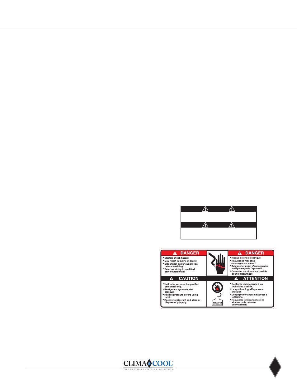
WARNING!
WARNING! To avoid possible injury or death due to electrical
shock, open the power supply disconnect switch and secure it
in an open position during installation .
CAUTION!
CAUTION! Use only copper conductors for field installed
electrical wiring . Unit terminals are not designed to accept
other types of conductors .