Water piping, Temperature sensor and wells, Pressure differential flow sensor – ClimaCool UGW Manual User Manual
Page 12: Pressure taps, Water isolation valves, Strainers – minimum 60 mesh screen required, Chiller/heater system water header bypass, Figure 7 - reverse return, Figure 6 - direct return
www.climacoolcorp.com
10
Water Piping
As with any water system, it is important that the system
be clean . The pipe work installer must remove weld scale,
rust and contamination during pipe work fabrication .
The system water piping must be flushed thoroughly
with recommended alkaline flush or other chemicals that
are compatible with 316 stainless steel, prior to making
connections to the ClimaCool chiller . There are certain
necessary components that should always be installed
in both the chilled water and condenser water systems .
(See Water Piping Configuration Figures 9 and 10 on page
12). Piping configurations on multiple modules may also
be found on page 12 . All water piping must be installed in
accordance with applicable codes and standards .
Temperature Sensor and Wells
ClimaCool provides four (4) temperature sensors and wells
with each chiller system configured by the CoolLogic Control
System. They must be field installed 36” - 60” away from
the bank and before the strainer on the chilled water inlet,
chilled water outlet, condenser water inlet and condenser
water outlet (See Water Piping Configuration – page 12).
Note: Sensors must be fully inserted into the well to obtain
proper readings.
Pressure Differential Flow Sensor
It is imperative that minimum and maximum water flow
rates, as defined in the Physical Data tables on page 5, are
not exceeded . To prevent operation of the chiller without
sufficient water flow to the evaporator and condenser, it
is required to install pressure differential flow sensors in
both the chilled and condenser water circuits . Place one
on each side, downstream of the strainers on the inlet and
outlet of a straight pipe, as close to the module as possible .
Do not put in an elbow on the outlet. (See Water Piping
Configuration – page 12). Note: Evaporator and condenser
sides both require sensors of equal pressure ranges.
Pressure Taps
The installing contractor must provide access ports for
connecting both the pressure differential flow sensor and
pressure gauges for both the condenser and chilled water
systems . A ¼” pressure tap is required on the inlet and the
outlet of both water systems for a total of eight (8) taps. If a
port is shared by the pressure differential flow sensor and the
pressure gauge, it will require four (4) ½” taps. (See Water
Piping Configuration – page 12).
Water Isolation Valves
It is recommended to provide bank water isolation valves
for proper isolation and maintenance of the chiller, pump
and strainer (See Water Piping Configuration – page 12).
Strainers – Minimum 60 Mesh Screen Required
ClimaCool chillers utilize brazed plate heat exchangers
which are extremely sensitive to debris . Therefore, it is
mandatory that all condenser and chilled water systems
include a strainer with a minimum of 60 mesh screen for
proper filtration. The strainers must be installed as shown in
the Water Piping Configuration on page 12 and be in place at
all times when the chiller(s) is/are in operation.
ClimaCool’s warranty does not cover and does not apply to
products which have defects or damages due to freezing
of the water supply, an inadequate or interrupted water
supply, corrosives or abrasives in the water supply, or
improper or inadequate filtration or treatment of the
water supply.
Chiller/Heater System Water Header Bypass
A bypass is required for any chilled water/evaporator, hot
water/condenser (heating load) and source water side
(geothermal, cooling tower or closed circuit cooler) with
variable pumping . The bypass must be piped in such a way
that the temperature and differential pressure sensors are
still sensing active flow. See Water Piping Configuration
Figures 9 and 10 on page 12 . The purpose of the chiller/
heater system bypass is to prevent deadheading of the
pumps when all of the internal unit valves go closed as well
as allow temperature and differential pressure sensors
to sense active flow. The bypass should be sized for an
absolute minimum of one module’s worth of design flow.
(Please refer to selection submittals for design flow rates).
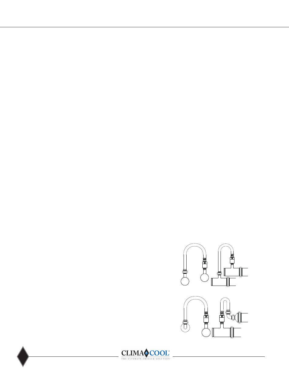
HEADER BYPASS
REVERSE RETURN
No.10
2" 90°
No.50
Reducer
6 x 2
Module
Header
No. 29 Reducing Tee
w/Thd. Branch
6 x 6 x 2
Module
Header
SIDE VIEW
6"
Grooved
C
ou
pl
in
g
6"
Grooved
C
ou
pl
in
g
2"
Gro
oved
Co
up
lin
g
Hose Kit
2"
Grooved
Coupling
2" Belimo
Ball Valve &
Actuator
No. 29 Reducing Tee
w/Thd. Branch
6 x 6 x 2
END VIEW
No.10
2" 90°
Elbow
No.50 Reducer
6 x 2
Hose Kit
2" Belimo
Ball Valve &
Actuator
2"
Grooved
Coupling
Figure 7 - Reverse Return
No. 25 Grooved Branch
6 x 6 x 2
Module
Header
6"
Grooved
C
ou
pl
in
g
HEADER BYPASS
DIRECT RETURN &
SIMULTANEOUS HTG & CLG
No. 29 Reducing Tee
w/Thd. Branch
6 x 6 x 2
Module
Header
6"
Grooved
C
ou
pl
in
g
SIDE VIEW
No. 25 Grooved Branch
6 x 6 x 2
No. 29 Reducing Tee
w/Thd. Branch
6 x 6 x 2
END VIEW
Hose Kit
2" Belimo
Ball Valve &
Actuator
2"
Grooved
Coupling
2" Belimo
Ball Valve &
Actuator
Hose Kit
2"
Grooved
Coupling
No. 25 Grooved Branch
6 x 6 x 2
Module
Header
6"
Grooved
C
ou
pl
in
g
HEADER BYPASS
DIRECT RETURN &
SIMULTANEOUS HTG & CLG
No. 29 Reducing Tee
w/Thd. Branch
6 x 6 x 2
Module
Header
6"
Grooved
C
ou
pl
in
g
SIDE VIEW
No. 25 Grooved Branch
6 x 6 x 2
No. 29 Reducing Tee
w/Thd. Branch
6 x 6 x 2
END VIEW
Hose Kit
2" Belimo
Ball Valve &
Actuator
2"
Grooved
Coupling
2" Belimo
Ball Valve &
Actuator
Hose Kit
2"
Grooved
Coupling
Figure 6 - Direct Return