Refrigeration system re-processing and charging, Interface board, Operation and troubleshooting – ClimaCool UGW Manual User Manual
Page 52
www.climacoolcorp.com
50
Refrigeration System Re-Processing and Charging
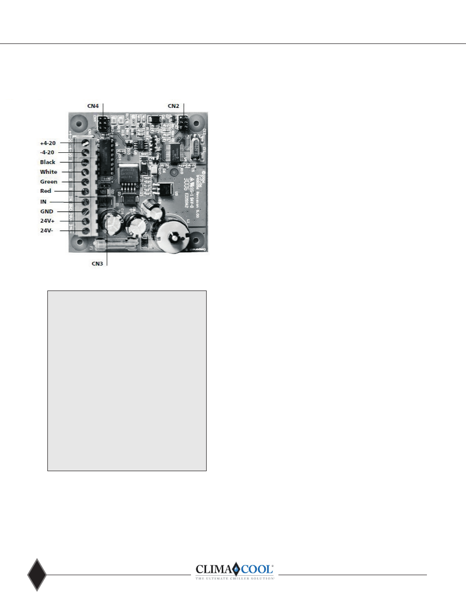
Figure 18 - Interface Board
Figure 19 - Wiring Connections
Interface Board
Factory installed interface board allows externally supplied
control signals to control electronic expansion valve .
Operation and Troubleshooting
When properly configured and installed, the interface board
requires no maintenance . The interface board incorporates
a number of operational features to assure trouble free
service . On power-up, the board will initialize by giving
the valve a large number of steps to assure that the valve
is fully shut .
The routine will require approximately 8 seconds for the
interface board 1, 16 seconds for the interface board 2 and
interface board 3 and 32 seconds for the interface board 6 .
The valve will not respond to input signals during this time .
The interface board is supplied with an onboard fuse and one
spare fuse . If a replacement fuse is not available, a 1 amp 250
volts delay fuse type GMC1 or equivalent may be used . The fuse
is designed to prevent board damage from miswiring . If the
fuse fails, correct wiring in accordance to all recommendations
before restoring power .
If the valve is required to shut during operation, the pumpdown
terminals should be used . When given a pumpdown signal, the
board will shut the valve immediately and overdrive by 250 steps
to reset valve position . On removal of the pumpdown signal, the
valve will resume position as dictated by the external control
signal . If power is lost to the interface board or wire to the valve
is severed, the valve will remain in its last position .
To force the valve shut during operation for test purposes,
simply remove the jumper from CN4 or CN3, depending on
configuration. To resume normal operation, replace the jumper.
To allow for component tolerances, the IB will shut the valve
when the input signal reaches 4 .05 milliamps or 0 .05 volts
depending on the configuration.
The interface board can power one or two valves . The valves
will operate simultaneously and will open and close by the same
number of steps . Both valve wires must be connected in the
proper color sequence .
If a step motor is suspected to have failed, a simple resistance
check may be made of the motor windings, however, actual
winding failures are rare .
From left to right when the board is oriented with
the terminal strip across the bottom.
connection for the positive leg of a 4-20 milliamp
or 0-10 volt signal
connection for negative leg of a 4-20 milliamp or
0-10 volt signal
black wire from valve or both valves when two
valves are used
white wire from valve or both valves when two
valves are used
green wire from valve or both valves when two
valves are used
red wire from valve or both valves when two
valves are used
from external pumpdown switch or relay . See
wiring instructions .
to external pumpdown switch or delay . See
wiring instructions .
from 24 volt, 40 VA transformer . See wiring
instruction .
from 24 volt, 40 VA transformer . See wiring
instruction .
+4-20
-4-20
B
W
G
R
IN
GND
24V+
24V-
Note: Power supplied may be 24 volts AC or DC