3 front panel controls, 4 back panel controls – B&K Precision 4078 - Manual User Manual
Page 17
6. Mode Display
- Displays the current mode selected. The can be continuous,
trigger, burst, or gate (displayed as CONT , TRI, BURST, or
GATE respectively). Refer to section 3.6.2 for details.
3.3 Front Panel Controls
The front-panel controls select, display, and change parameter, function, and mode settings. They also include the keys
you use to program and generate arbitrary waveform output. Refer to Figure 3.1.
Use the rotary input knob and the cursor movement keys to enter data into the waveform generator.
To change a setting:
1. Press any FUNCTION keys (F1 – F4) that lead to a required item.
2. Move cursor using CURSOR keys to the appropriate position in the numeric field (if applicable).
3. Use the rotary input or the numerical KEYPAD to change the value of the displayed item. Changes take effect
immediately.
4. In some parameter settings, the ENTER key must be pressed in order to set their numerical/setting values.
Otherwise, it may not save.
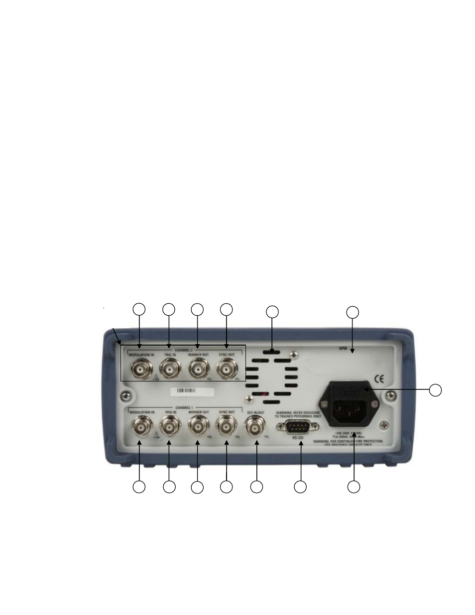
3.4 Back Panel Controls
The function generator has nine (five for model 4075) BNC Connectors on the rear panel where you can connect
coaxial cables. These coaxial connectors are labeled accordingly on the back panel for their respective channels and
serve as carrier lines for input and output signals delivered to and from the function generator.
Figure 3.3 - Back Panel View
1. Modulation In - 5 Vp-p signal for 100% modulation, 10Kohms input impedance with DC - >20 KHz
bandwidth. This connector can be used for modulating external signals in AM and FM modulation.
2. Trig In - Use this connector to apply an external trigger or gate signal, depending on the waveform
(For CH2 : Model
4078 only)
1
1
2
2
3
3
4
4
5
6
7
8
9
10