6 power requirements, 7 grounding requirements, 8 signal connections – B&K Precision 4078 - Manual User Manual
Page 12: 9 rs-232 connection
2.6 Power Requirements
The Model 4075 and 4078 can be operated from any source of 90 V to 264 V AC, frequency from 48 Hz to 66 Hz.
The maximum power consumption is 50 VA. Use a slow blow fuse UL/CSA approved of 1 A as indicated on the rear
panel of the instrument.
The instrument power fuse is located in the AC input plug. To access the fuse, first disconnect the power cord and
then remove the fuse cartridge.
2.7 Grounding Requirements
For the safety of operating personnel, the instrument must be grounded. The central pin on the AC plug grounds the
instrument when properly connected to the ground wire and plugged into proper receptacle.
WARNING
TO AVOID PERSONAL INJURY DUE TO SHOCK, THE THIRD WIRE EARTH GROUND MUST BE
CONTINUOUS TO THE POWER OUTLET. BEFORE CONNECTION TO THE POWER OUTLET,
EXAMINE ALL CABLES AND CONNECTIONS BETWEEN THE UNIT AND THE FACILITY POWER
FOR A CONTINUOUS EARTH GROUND PATH.
THE POWER CABLE MUST MEET IEC SAFETY STANDARDS.
2.8 Signal Connections
Use RG58U 50
Ω or equivalent coaxial cables for all input and output signals to and from the instrument.
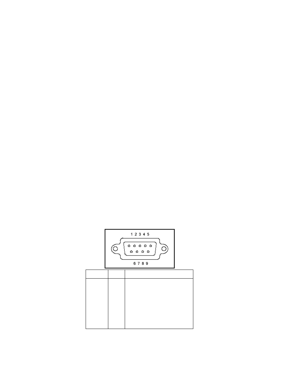
2.9 RS-232 Connection
The rear panel RS-232 connector is a standard DB-9 male connector configured as a DCE. The pin assignments are
defined in the table below:
DB-9 pin Name
Note
1
2
3
4
5
6
7
8
9
-
TXD
RXD
-
GND
-
RTS
CRS
-
-
Transmit Data
Receive Data
-
Signal ground
-
Request to Send
Clear to send
-
*Note: Use a Null-modem or cross over cable (pin 2 and 3 switched) in order to communicate with instrument. When
transmitting large files, use only RS232 to RS232 (female to female) cables with no more than 50FT in length. Baudrate
of 9600 and 19200 are recommended values when configuring the interface.