0 operation, 1 start-up and test – Alpha Technologies APX Series User Manual
Page 40
40
016-030-B0-005, Rev. C
Test Procedure:
Before you apply power, verify that the AC LINE circuit breaker is in the OUT (off)
position. The white portion of the stem will be visible. If it is not, press the breaker button.
Plug the APX power plug into the receptacle provided in the internal AC receptacle box.
If the APX is equipped with a LA-M (or LA-P) Plug-in MOV, plug it into the designated
receptacle.
Switch the external service entrance breaker (located outside of the enclosure) to ON.
To reset the APX internal AC LINE circuit breaker, press the button (the white portion on
the stem will not be visible).
Measure the output voltage at the APX output connector, using a true reading RMS digital
multimeter. An acceptable voltage range is between 57 and 63 VAC for 60VAC output
models (45.6 to 50.4 for 48V models).
If the AMM-C Ammeter option is installed (APX models only), ensure that the current
draw is in the correct range, (for example, below 8A for 8A units, and below 14A for 14A
units).
Place the cover on the APX, aligning the tabs on the cover with the base plate assembly.
Secure the hold-down screw and lock the enclosure.
1.
2.
3.
4.
5.
6.
7.
8.
3.0 Operation
3.1 Start-up and Test
After all utility and cable connections are complete, test the APX before placing it into service.
NOTE:
In Step 6, if a non-RMS type voltmeter is used, the reading may be off by as much as 10% due to the
“quasi” square wave output of the ferroresonant transformer.
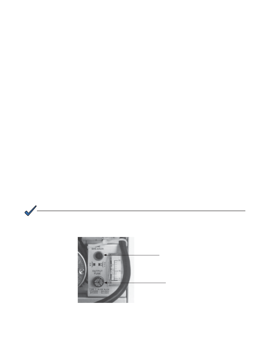
Input AC Line
Breaker
AC Output
Fuse
Fig. 3-1, APX Circuit Breaker and Fuse Location