5 shelf mount installations – Alpha Technologies APX Series User Manual
Page 22
22
016-030-B0-005, Rev. C
Procedure
:
To place the modular transformer assembly (MTA) on the shelf mount (SM), fi t the slot on
the top of the MTA over the tab on the SM bracket.
Locate the captive screw on the opposite side of the shelf mount adaptor (next to the
terminal block). Fit the captive screw into the threaded portion of the MTA and tighten.
Place the assembled shelf mount bracket and modular transformer assembly into the
shelf of the enclosure (PED-M, PWE or UPE). Place one of the key-slot holes over the
threaded screw hole in the enclosure shelf. Install a 8-32 x 1/2" long screw and tighten.
Connect the AC input power extension cable to the AC power cable on the unit. Connect
the plug of the extension cable into the AC receptacle.
Output connection to the plant is accomplished via the terminal block or by using the
APX- SPI adaptor cable.
The APX is now ready to connect to utility power via the terminal block on the MTA (see
Section 3.1 Start-up and Test).
1.
2.
3.
4.
5.
6.
NOTE:
Before you install the MTA, fi rst install and connect all optional features..
NOTE:
Only one screw hole is used to mount the SM to the enclosure shelf. To install additional APX-SM units
in the enclosure, drill and tap another mounting hole.
2.0 Installation,
continued
2.5 Shelf Mount Installations
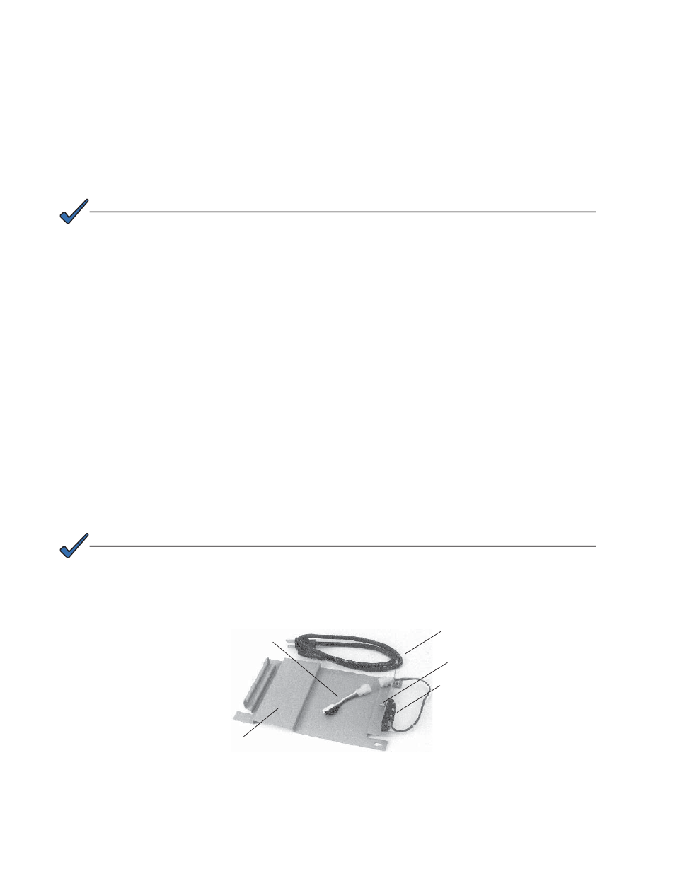
The shelf mount version of the APX consists of the standard MTA (Modular Transformer
Assembly) which rests on a mounting plate (SM). You can install the mounting plate and
MTA into a number of Alpha enclosures, including the PED-M, PWE or UPE. The shelf mount
option also includes an input AC power extension cable (APX model only) and an APX-SPI
adaptor.
Power Extension Cable
APX Output Connection Block
SPI Adaptor Cable
Shelf Mount
Captive Screw
Fig. 2-10, Shelf Mount (SM)