Alpha Technologies APX Series User Manual
Page 26
26
016-030-B0-005, Rev. C
Procedure (230VAC, 50 HZ):
If the MTA is installed, completely remove it prior to utility wiring. To remove the
transformer assembly, loosen the captive screw on the bottom of the baseplate
and lift.
Loosen the two captive screws securing the receptacle box. Turn receptacle box
over to expose the internal wiring.
Route utility conduit through the 7/8" diameter opening at the bottom of the APX
PM Enclosure. Secure the fi tting with a lock nut.
Connect the utility brown-hot wire (230VAC; 50Hz) to the brown wire inside re-
ceptacle box using existing wire nut.
Connect blue-neutral wire to the blue wire inside the receptacle box using the
existing wire nut.
Connect utility green/yellow tracer -ground wire to the grounding wire clamp on
the baseplate. Tighten clamping screw. An external grounding clamp is also pro-
vided on the outside of the enclosure for connection to a ground-rod.
Reposition the rear tab on the receptacle box into the slot in the baseplate.
Tighten the two captive screws.
Reinstall the MTA and tighten screw.
1.
2.
3.
4.
5.
6.
7.
8.
2.0 Installation,
continued
2.6
Connecting Utility Power, continued
2.6.1
Wiring the Enclosure Utility Service, continued
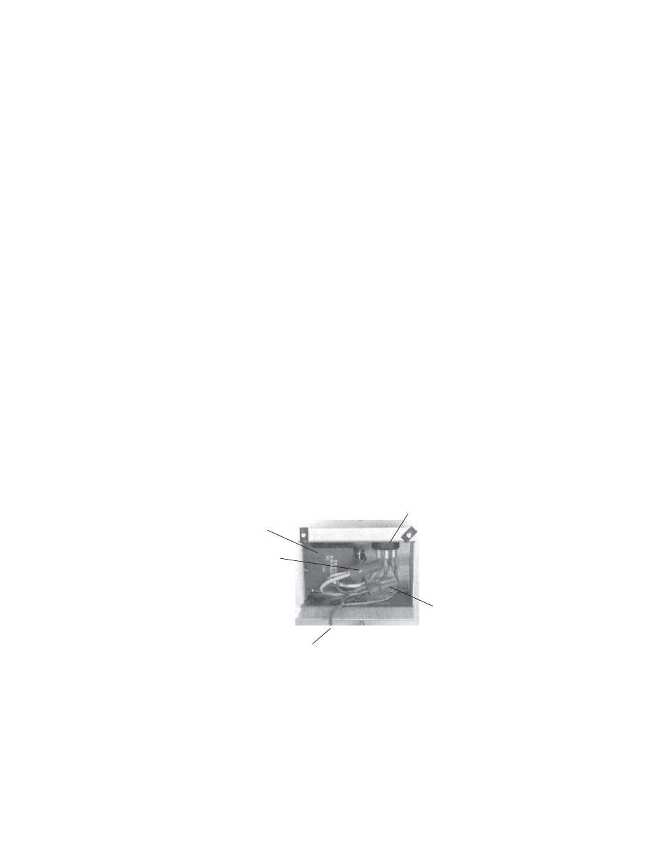
Fig. 2-15, APX 230VAC/50Hz Wiring
Grounding Wire
(Green/Yellow Tracer)
MTA Power Receptacle
Neutral Wire
(Blue 230VAC/50Hz)
Hot Wire
(Brown 230VAC/50Hz)
LA-E