Alpha Technologies APX Series User Manual
Page 25
25
016-030-B0-005, Rev. C
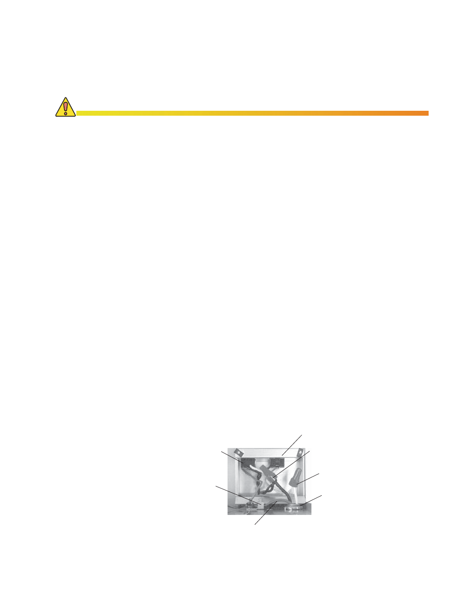
Procedure (120VAC, 60HZ)
:
If the Modular Transformer Assembly (MTA) is installed it must be completely
removed during utility wiring. To remove the transformer assembly, loosen the
captive screw on the bottom of the baseplate and lift.
Loosen the two captive screws securing the receptacle box. Turn the receptacle
box over to expose the internal wiring.
Route the utility conduit through the 7/8" diameter opening located at the bottom
of the APX. Secure the fi tting with a locknut.
Connect the utility black (hot) wire (120VAC; 60Hz) to the black wire inside the
receptacle box using the existing wire nut.
Connect the white (neutral) wire to the white wire inside the receptacle box us-
ing the existing wire nut.
Connect the utility green with yellow tracer ground wire to the grounding-wire-
clamp on the baseplate and tighten the clamping screw. An external grounding
clamp is also provided on the outside of the enclosure for connection to a
ground-rod.
Reposition the rear tab on the receptacle box into the slot in the baseplate.
Tighten the two captive screws.
Reinstall the MTA and tighten the screw.
1.
2.
3.
4.
5.
6.
7.
8.
CAUTION!
Before you begin, turn off all utility power. Do not plug APX into AC receptacle at this time.
2.0 Installation,
continued
2.6
Connecting Utility Power, continued
2.6.1
Wiring the Enclosure Utility Service, continued
Fig. 2-14, 120VAC/60Hz Wiring
Grounding Wire
(Green)
LA-M Receptacle
Grounding Lug
(Internal)
120VAC Utility Input
MTA Power Receptacle
Neutral Wire
(White 120VAC/60Hz)
Hot Wire
(Black 120VAC/60Hz)