Alpha Technologies APX Series User Manual
Page 34
34
016-030-B0-005, Rev. C
Procedure, Wiring the LA-E lightning arrestor:
If the MTA is installed, remove it from the baseplate.
Remove the two screws from the front fl ange of the receptacle housing and lift it up to
expose the wires underneath.
Remove the center screw from metal base of the LA-E option (if installed) and fi t the LA-
E into the left side of the receptacle housing. Replace the screw (removed in Step 2) from
the outside of the receptacle housing and tighten.
Connect the brown wire from the LA-E to the brown (hot) wire in the receptacle box. This
wire also connects to the brown (hot) wire from the utility. Use the existing wire nut to
connect and secure the wires.
Connect the BLUE wire from the LA-E to the blue (neutral) wire in the receptacle box.
This wire also connects to the blue (neutral) wire from the utility. Use the existing wire nut
to connect and secure the wires.
If wiring to the utility at this time, follow steps 4 and 5 above. Reposition the receptacle
box back onto the baseplate and replace the two screws.
1.
2.
3.
4.
5.
6.
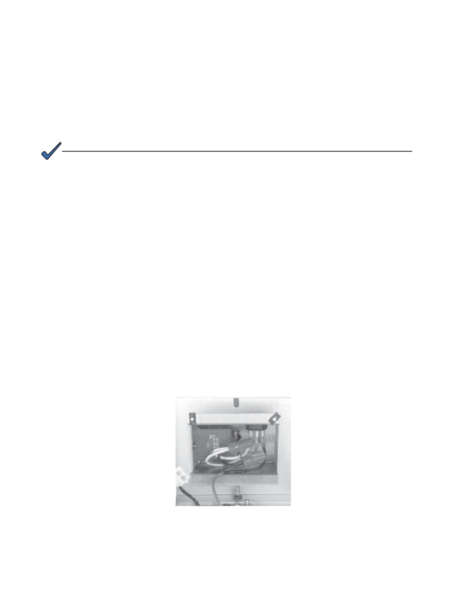
LA-E (Lightning Arrestor for APX-E Version)
The LA-E lightning arrestor is hard-wired into the receptacle housing of the APX base unit.
Install the device when initially wiring the APX to the 230VAC mains.
NOTE:
The APX-E receptacle box does not contain a separate receptacle for the LA-E.
2.0 Installation,
continued
2.10 Options,
continued
.
Fig. 2-24, LA-E Option (230VAC models)
Mounted Under Receptacle Box