Alpha Technologies APX Series User Manual
Page 15
15
016-030-B0-005, Rev. C
2.1.2 Concrete and Steel Poles
Materials Required:
Two (2) 1-1/2" approved mounting straps, length to suit pole.
Tools Required:
Assorted sockets or wrenches
Procedure:
Mark the position for the upper mounting strap on the utility pole.
Run two approved 1-1/2" mounting straps through the mounting bracket located
on the back of the baseplate assembly.
Center the baseplate assembly on the pole and tighten the mounting straps.
Install the Modular Transformer Assembly (MTA) onto the baseplate (see Section
2.8 for details).
1.
2.
3.
4.
2.0 Installation,
continued
2.1
Pole Mount Installations, continued
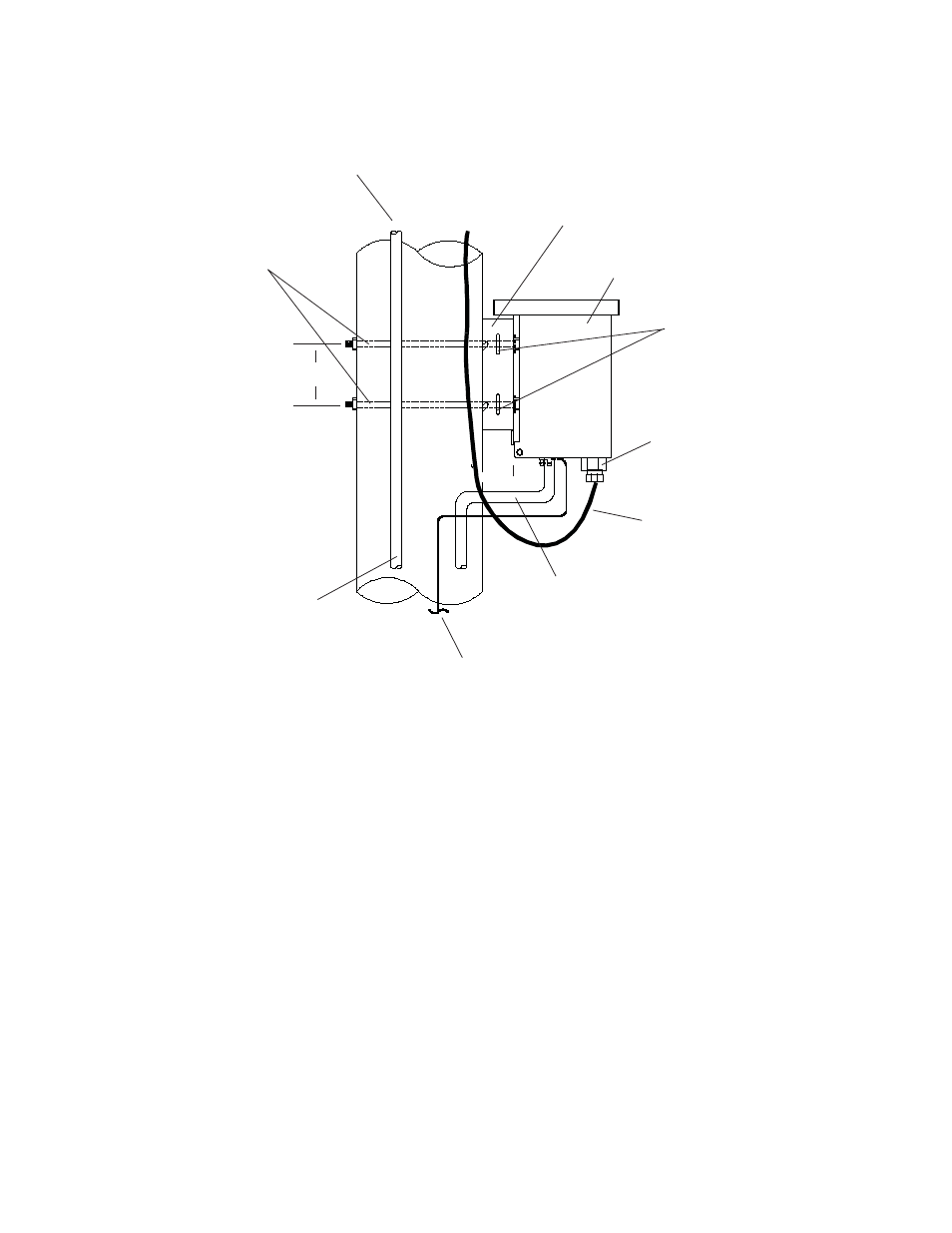
Fig. 2-1, APX Enclosure Pole Mounting
VSF Output Connector
NOTE: If mounting to a
steel or concrete pole, use
these two strap slots
#8 AWG (Minimum)
Copper Ground Wire
Cable Output
Utility Power Input
(from Service Entrance)
Enclosure Mounting Bracket
5/8" Diameter Bolts and
Associated Hardware
Service Drop
To Service
Entrance
APX Enclosure
4 1/2”
center-center
- AlphaCell GelCell Series (32 pages)
- FXM 650, 1100, 2000 UPS (96 pages)
- Cordex 48-1.2kW (68 pages)
- Radium MiniBay (57 pages)
- Fiber Backhaul Enclosure (FBE) (19 pages)
- FBE2322 Enclosure System (38 pages)
- FlexNet PMR, GMR Series (49 pages)
- Te25xh (38 pages)
- FlexNet MPS48-12M - Technical Manual (33 pages)
- FlexNet MPS48-12M - Quick Start Guide (2 pages)
- FlexNet ELPM 300-48D (25 pages)
- FlexNet FMPS (40 pages)
- FlexPoint AX Series (34 pages)
- FlexPoint FPR1207-F - Technical Manual (18 pages)
- FlexPoint FPR1207-F - Quick Start Guide (2 pages)
- AlphaGen PN-6x-T 7.5kW 48VDC - Installation and Operation Manual (79 pages)
- AlphaGen CE-3x2 5K-T 48Vdc (95 pages)
- AlphaGen PN-6x-T 7.5kW 48Vdc (95 pages)
- AlphaGen 3.5_5.0kW Kohler COM5 (80 pages)
- Security Bar Field For UPE-3, UPE-6, UPE-M3, UPE-M6, PN Series and CE Series (2 pages)
- AMPS80 HP (116 pages)
- 255A Bypass Switch (24 pages)
- AMP24 HP (108 pages)
- FXM350_Micro350 UPS (112 pages)
- CFR 600, CFR 600XT, CFR 1000 (70 pages)
- BPS Series Bypass Switch (36 pages)
- CFR Intelligent Interface Device (54 pages)
- CFR Redundant Control Unit (23 pages)
- CFR 5000, CFR 5000RM (88 pages)
- CFR 3000, CFR 3000RM (86 pages)
- CFR 1500, CFR 1500RM (83 pages)
- CFR 1500, CFR 2000, CFR 2500, CFR 3000 (76 pages)
- Continuity: 1000_2000_3000 (48 pages)
- Continuity Battery Pack (20 pages)
- Continuity: 6K_10K (52 pages)
- Micro, Micro XL, Micro XL3 UPS (99 pages)
- Micro Secure UPS (80 pages)
- Te17 (32 pages)
- Te45 (68 pages)
- Te41, 48V (76 pages)
- Te41, 24V (72 pages)
- Te43 (60 pages)
- AlphaGuard AG-CMT Installation (2 pages)
- AlphaGuard AG-CMT-3SC_4SC-P (2 pages)
- Digital Midtron DM-3200 AT (2 pages)