2 wall mount installations – Alpha Technologies APX Series User Manual
Page 16
16
016-030-B0-005, Rev. C
Install and connect all optional features before you install the MTA.
NOTE:
Procedure:
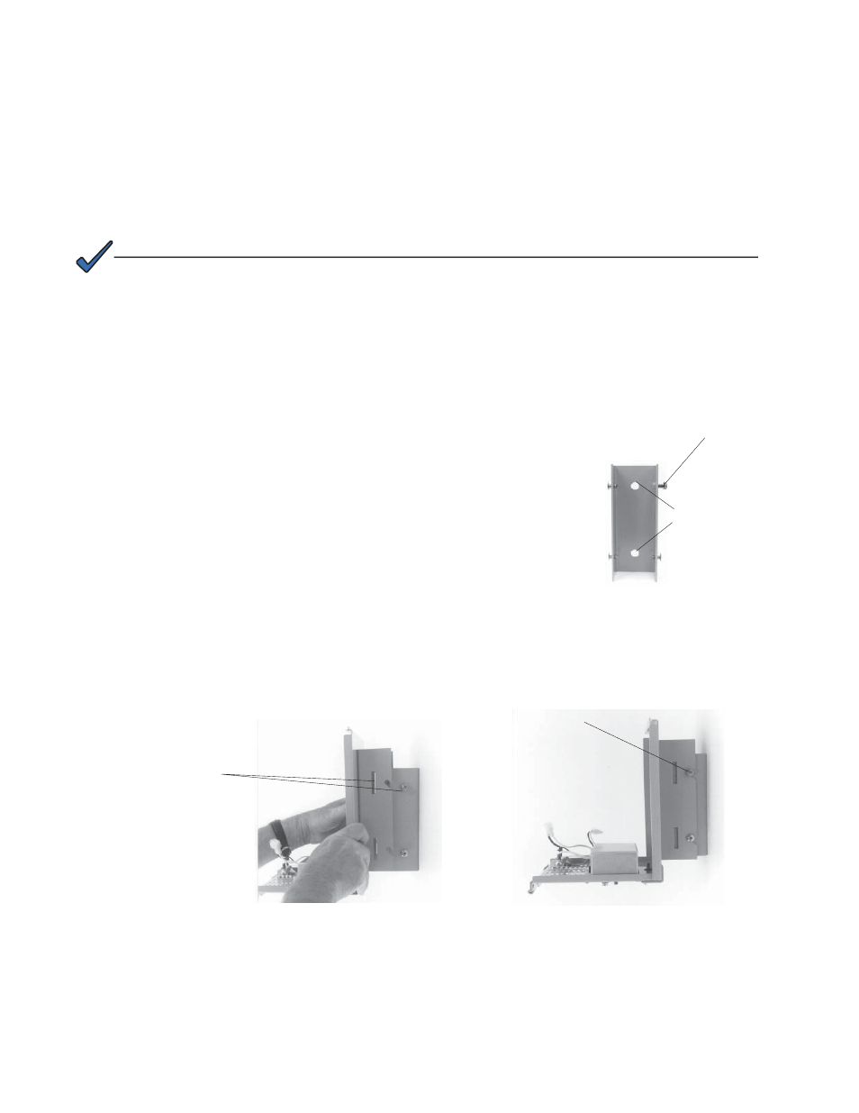
Mark the location of the wall mounting holes, using
the bracket as a template. The distance between the
holes is 4 1/2 inches center-to-center.
Drill the holes using a 1/4" drill bit. Mount the bracket
to the wall using two 3/8" x 1 1/2" long steel lag bolts
and washers. The 1/4-20 (Phillips) screw must be
located in the upper right-hand side of the bracket
before you secure it to the wall.
To mount the enclosure to the wall bracket, fi t the
slots (in the APX enclosure bracket) over the rivets in
the wall bracket. The enclosure bracket fi ts over the
outside of the wall bracket.
Tighten the screw located on the upper-right corner of
the wall bracket using a #2 Phillips head screwdriver.
Install the Modular Transformer Assembly (MTA) onto
the baseplate. See Section 2.8 for details.
1.
2.
3.
4.
5.
2.0 Installation,
continued
2.2 Wall Mount Installations
The wall mount version is equipped with an adaptor bracket to ensure that the APX pole
mount enclosure can be mounted on a fl at, vertical surface. If the wall mount bracket cannot
be installed on a fl at, vertical surface and positioned over a wall stud (2x4; 2x6; etc), use
appropriate anchors and lag bolts.
1/4-20 Screw
(upper-right hand
side)
Wall Mounting
Holes
Step 1, Wall Bracket
Align slots with rivets and screw
Step 2, Aligning slots
Tighten screw
Step 3, Tighten screw
Fig. 2-2, Wall Mount Installation