Wiring the host/config port, Wiring, The host/config port – Extron Electronics MLC 60 Series User Guide User Manual
Page 31: Ground wire to pin 3, which plugs into the, Ground) port, Mlc rs d rear panel
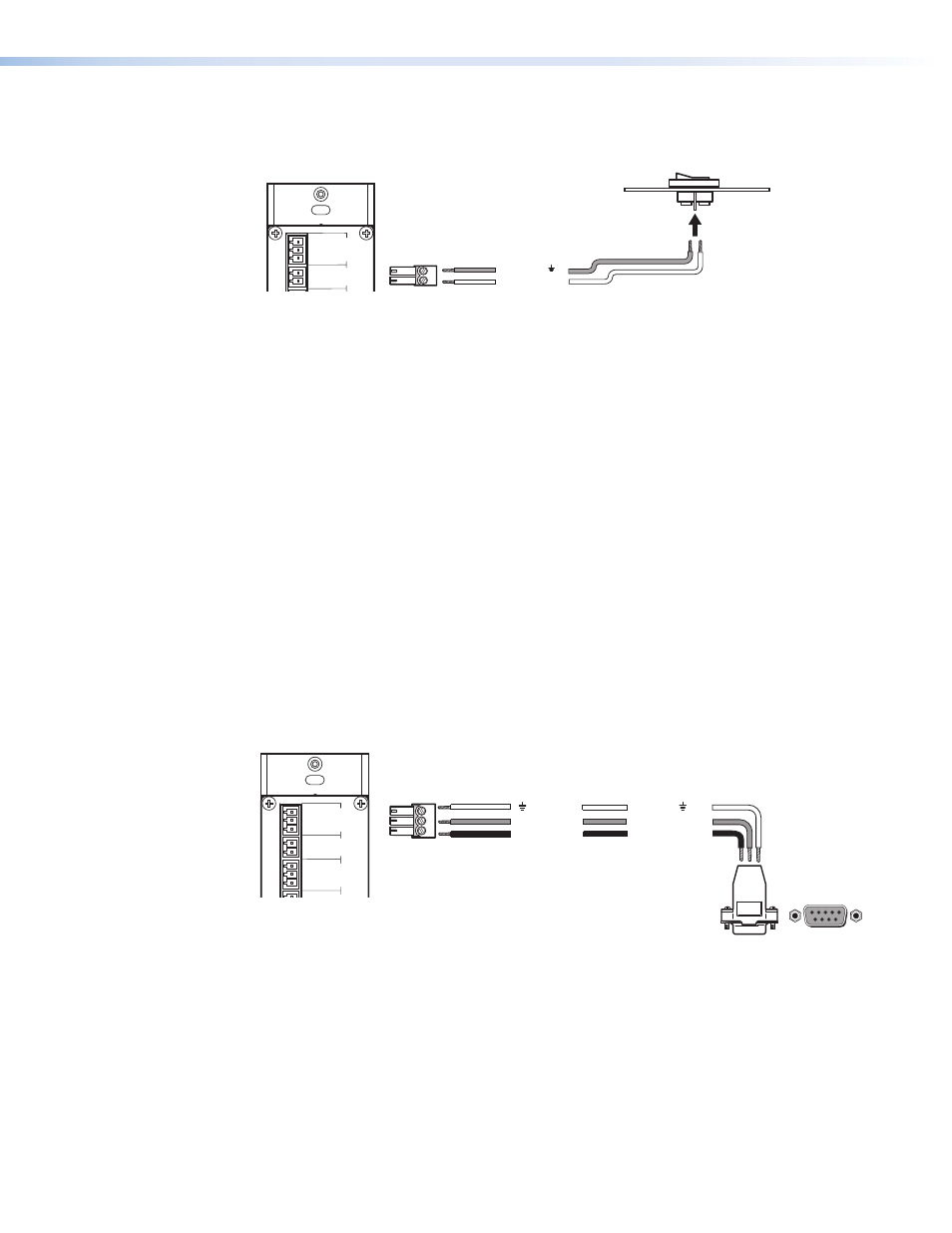
Example: The diagram below shows a two-position switch connected to the Digital Input
port of an MLC 62 RS D.
Ground ( )
Digital Input 1
Rx
Tx
GROUND
Tx/IR
COMMON
1
1
2
HOST/
CONFIG
RS-232
IR/
S
DIGITA
L
INPUT
Tx
PW
R
12
V
0.2 A MA
X
RELAYS
N/
O
GROUND
GROUND
GROUND
GROUND
+12 VDC
MLC RS D Rear Panel
Two-position Switch
1
2
Pin:
Figure 26.
Connecting a Two-position Switch to the Digital Input Port
Wiring the Host/Config Port
The Host/Config port provides an alternative connection by which the MLC can be
configured and controlled from a host device or computer. (The primary means of
configuring the MLC is through the USB port; see “
Configuring the MLC via the USB
,” later in this section.) In addition, SIS commands can be issued through this port
from the computer to control the MLC (see the “
The RS-232 protocol for this connection is 9600 baud, 1 stop bit, no parity, 8 data bits, no
flow control.
Use a female 9-pin to bare wire RS-232 cable or a universal control cable (such as
UC 50', Extron part number 26-518-01, or UC 100', part number 26-518-02) to connect
a Windows-based PC or an RS-232 control system to the MLC via this 3-pole, 3.5 mm
captive screw connector as follows:
1.
Wire the RS-232 cable to one of the 3-pole captive screw plugs provided with the
MLC, as follows:
•
Receive wire to pin 1, which plugs into the Tx (transmit) port
•
Transmit wire to pin 2, which plugs into the Rx (receive) port
•
Ground wire to pin 3, which plugs into the
_
(ground) port
Rx
Tx
GROUND
Tx/IR
COMMON
1
1
2
HOST/
CONFIG
RS-232
IR/
S
DIGITA
L
INPUT
Tx
PW
R
12
V
0.2 A MA
X
RELAYS
N/
O
GROUND
GROUND
GROUND
GROUND
+12 VDC
MLC 62 RS D Rear Panel
To RS-232 Port on Computer
or Control System
9 pin HD
Connector
Ground
Rx Receive
Transmit
Tx
3
Transmit (Tx)
Receive (Rx) 2
Ground ( ) 5
1
2
3
Pin:
5
1
9
6
Figure 27.
Connecting a Host Computer or Control System to the
Host/Config Port
2.
Plug the 3-pole connector into the Host/Config port on the MLC rear panel.
MLC 60 Series MediaLink Controllers • Features, Installation, and Operation
25