Extron Electronics ISS 108 User Manual
Page 87
7-5
Integration Seamless Switcher • Maintenance and Modifications
3.
If the rear panel DVI connector opening is still covered, remove the two
screws that secure the cover to the back panel and remove the cover.
4
.
Position the DVI card above connector J14 with the DVI connector facing
toward the rear of the switcher. Ensure that the pins on the DVI card
properly align with the J14 connector to prevent bending the pins.
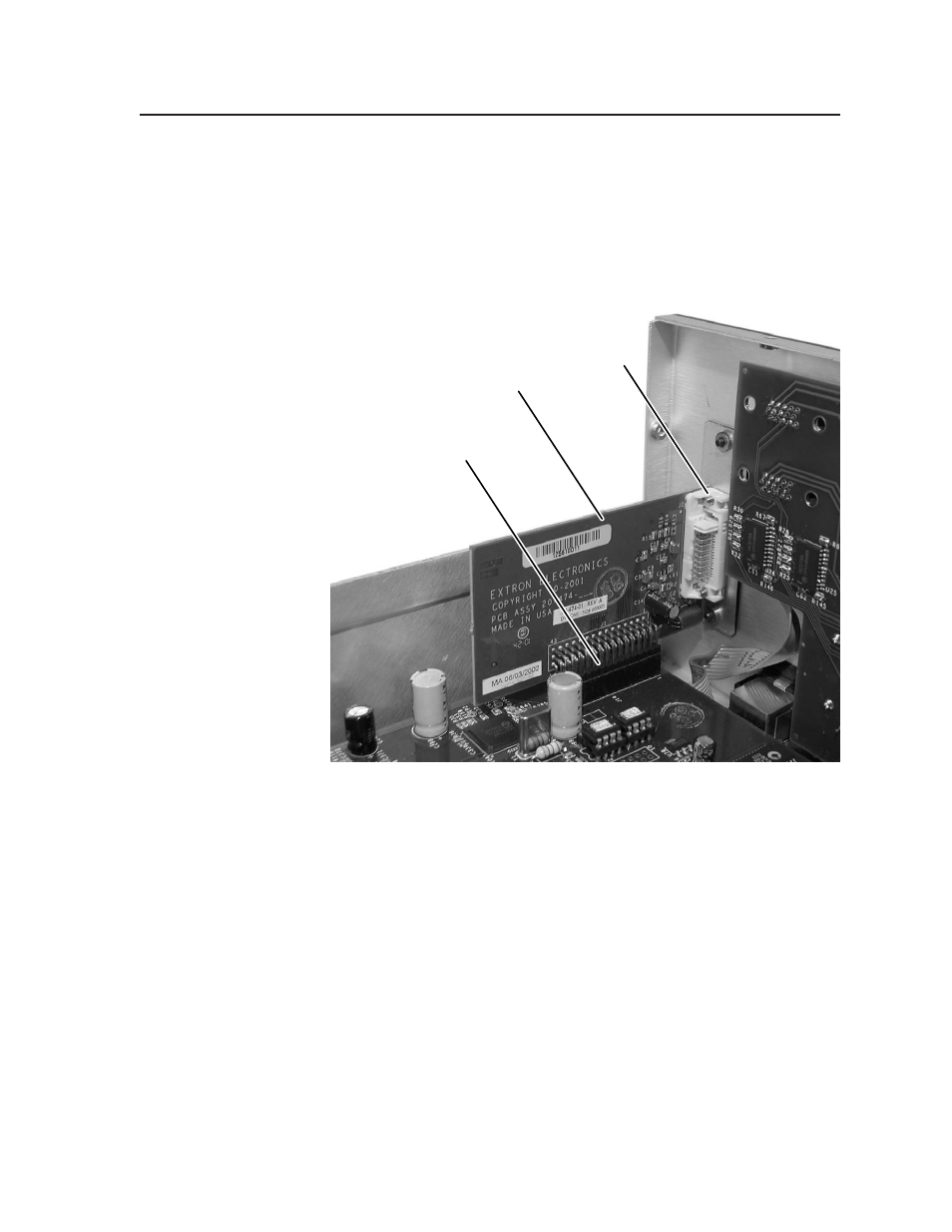
5.
Carefully mate the 45-pin connector on the DVI output board with
connector J14 on the main circuit board (figure 7-3).
DVI Output Card
Mated to the
Main Board via
Connector J14
DVI Output Card
DVI Output Card
DVI Connector
Figure 7-3 — Output DVI board installation
6.
Secure the DVI card to the rear panel with the two screws removed in step 3.
7
.
Close the switcher. See Opening and Closing the Switcher, starting on step 9,
on page 7-3.