Cabling and rear panel views, Input connections, 3 integration seamless switcher • installation – Extron Electronics ISS 108 User Manual
Page 17: All connectors are on the rear panel (figure 2-2)
2-3
Integration Seamless Switcher • Installation
Cabling and Rear Panel Views
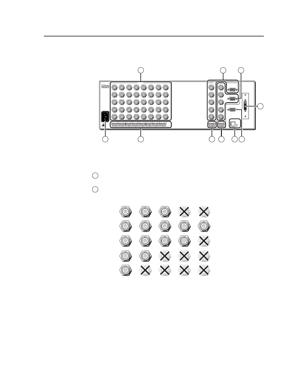
All connectors are on the rear panel (figure 2-2).
100- 240
50/60 Hz
1.2A MAX.
1
2
H/HV
V
3
H/HV
V
INPUTS
4
H/HV
V
5
H/HV
V
6
H/HV
V
7
H/HV
V
R/R-Y
8
G/Y
VID
B/C
B-Y
R/R-Y
G/Y
VID
B/C
B-Y
R/R-Y
G/Y
VID
B/C
B-Y
R/R-Y
G/Y
VID
B/C
B-Y
R/R-Y
G/Y
VID
B/C
B-Y
R/R-Y
G/Y
VID
B/C
B-Y
R/R-Y
G/Y
VID
B/C
B-Y
R/R-Y
G/Y
VID
B/C
B-Y
H/HV
V
PROGRAM
OUTPUTS
PROGRAM
PREVIEW
RS-232
DVI OUT
PREVIEW
2
3
4
5
6
7
8
H/HV
V
1
R
G
B
H/HV
V
R
G
B
H/HV
V
ETHERNET
LINK
ACT
1
6
7
9
2
10
8
3
4
5
Figure 2-2 — ISS 408 rear panel connectors
Input connections
1
AC power connector
— Plug a standard IEC power cord into this connector
to connect the switcher to a 100 to 240 VAC, 50 Hz or 60 Hz power source.
2
Input video connectors
— Connect computer or RGB video, component
video, S-video, or composite video to these female BNC connectors.
Figure 2-3 shows how to connect the various video formats.
H
/HV
RGBHV
Video
RGsB or
Component
Video
S-Video
Composite
Video
RGBS or
RGBcvS
Video
V
H/
HV
V
H/HV
V
H/HV
V
H/HV
V
R/R-Y
G/Y
VID
B/C
B-Y
R
/R-Y
G
/Y
VID
B
/C
B-Y
R
/R-Y
G
/Y
VID
B
/C
B-Y
R/R-Y
G/Y
VID
B
/C
B-Y
R/R-Y
G/
Y
VID
B/
C
B-Y
Figure 2-3 — Connections for various input video formats