Quick start — integration seamless switcher, Installation, Step 1 – Extron Electronics ISS 108 User Manual
Page 3: Step 2, Step 3, Step 4, Step 5, Step 6, Step 7, Step 8
QS-1
Quick Start — Integration Seamless Switcher
Installation
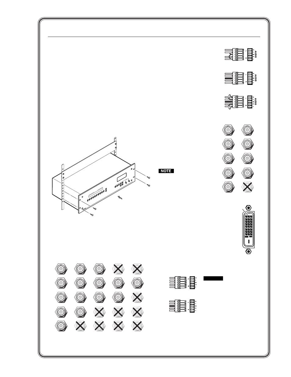
Step 1
Turn off power to the ISS 108 or ISS 408 and the
input and output devices, and remove the power
cords from them.
Step 2
If desired, install an optional DVI output card into
the switcher. See chapter 7, Maintenance and
Modifications.
Step 3
Install four rubber feet on the bottom of the ISS or
mount the ISS in a rack.
Step 4
Connect up to eight computer/RGB video,
component video, S-video, or composite video
sources to the female BNC input connectors. The
figure below shows how to connect the various
video formats.
BL
AC
K
1
2
3
4
5
6
7
8
VI
DE
O
CU
T
DI
SS
OL
VE
1
2
3
4
5
6
7
8
AU
DI
O
MU
TE
CO
LO
R/
TIN
T
BR
T/
CO
NT
SI
ZE
CE
NT
ER
FIL
TE
R
AD
JU
ST
ME
NU
NE
XT
OU
TP
UT
S
IS
S
40
8
IN
TE
GR
AT
IO
N
SE
AM
LE
SS
S
W
ITC
HE
R
H/
HV
R
G
B
H
/HV
RGBHV
Video
RGBS
Video
V
R
G
B
V
H
/HV
RGBHV
Video
RGsB or
Component
Video
S-Video
Composite
Video
RGBS or
RGBcvS
Video
V
H/
HV
V
H/HV
V
H/HV
V
H/HV
V
R/R-Y
G/Y
VID
B/C
B-Y
R
/R-Y
G
/Y
VID
B
/C
B-Y
R
/R-Y
G
/Y
VID
B
/C
B-Y
R/R-Y
G/Y
VID
B
/C
B-Y
R/R-Y
G/
Y
VID
B/
C
B-Y
Unbalanced Input
Tip
Sleeve
Tip
Sleeve
Balanced Input
Tip
Ring
Sleeve (s)
Tip
Ring
Tip
Ring
Sleeve (s)
Tip
Ring
Balanced Input
(high impedance)
(high impedance)
(600 ohms)
600 ohms
600 ohms
1
9
8
17
24
Step 5
Cable the switcher for
stereo audio input. Each
input has a 3.5 mm, 5-pole
captive screw connector for
balanced or unbalanced
stereo or mono audio
input. Connectors are
included with each
switcher, but you must
supply the audio cable.
High impedance is
generally over 800 ohms.
Step 6
Connect RGB video displays to
the Preview output and
Program output female BNC
and 15-pin HD connectors.
Connect the various video
formats to the BNC connedtors
as shown.
Both output connector
types output the same
video signal and the
same sync format.
Step 7
If the optional DVI output card is
installed
, connect a DVI video display
to the Program output DVI connector.
Step 8
Cable the switcher for stereo audio
output. Each output has a 3.5 mm,
5-pole captive screw connector that
outputs the selected unamplified, line
level audio. Connect an audio device,
such as an audio amplifier or powered speakers.
A
UDIO
A
UDIO
Unbalanced Output
Tip
See caution
Sleeve
Tip
See caution
Balanced Output
Tip
Ring
Sleeve (s)
Tip
Ring
CAUTION
Connect the
sleeve to ground.
Connecting the
sleeve to a
negative (-)
terminal will
damage the audio
output circuits.