Extron Electronics ISS 108 User Manual
Page 21
2-7
Integration Seamless Switcher • Installation
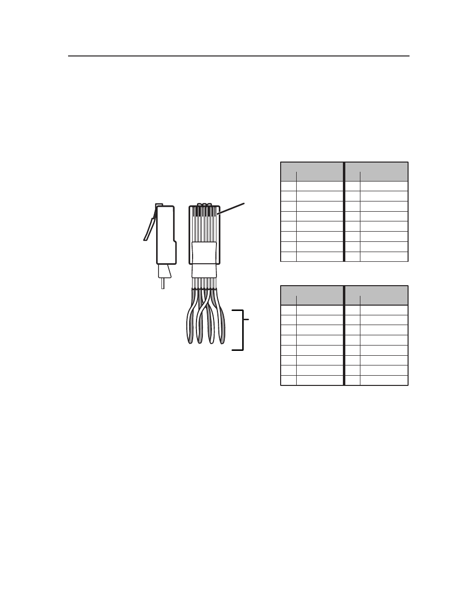
Wiring the network cable
The cable can be terminated as either a patch cable or a crossover cable (figure 2-8)
and must be properly terminated for your application:
•
Patch (straight) cable —
Connection of the ISS to an Ethernet hub, router, or
switcher that also hosts a controlling computer.
•
Crossover cable —
Direct connection between the ISS and a controlling
computer.
Clip Down
Side
1
1&2
3&6 4&5
7&8
2 3 4 5 6 7 8
1
Pins
2 3 4 5 6 7 8
RJ-45
connector
Patch (straight) cable
Twisted
Pairs
Side 1
Side 2
Pin
Wire color
Pin
Wire color
1
White-orange
1
White-orange
2
Orange
2
Orange
3
White-green
3
White-green
4
Blue
4
Blue
5
White-blue
5
White-blue
6
Green
6
Green
7
White-brown
7
White-brown
8
Brown
8
Brown
Crossover cable
Side 1
Side 2
Pin
Wire color
Pin
Wire color
1
White-orange
1
White-green
2
Orange
2
Green
3
White-green
3
White-orange
4
Blue
4
Blue
5
White-blue
5
White-blue
6
Green
6
Orange
7
White-brown
7
White-brown
8
Brown
8
Brown
Figure 2-8 — RJ-45 connector pinout table