Programmer’s guide, Rs-232 link, Ethernet link – Extron Electronics ISS 108 User Manual
Page 48
Integration Seamless Switcher • Programmer’s Guide
4-2
Programmer’s Guide
RS-232 Link
The switcher’s rear panel Remote 9-pin D female connector (figure 4-1) can be
connected to the RS-232 serial port output of a host device such as a computer
running the HyperTerminal utility or a control system. This connection makes
software control of the switcher possible.
RS-232
Function
Pin
1
2
3
4
5
6
7
8
9
—
TX
RX
—
Gnd
—
—
—
—
Not used
Transmit data
Receive data
Not used
Signal ground
Not used
Not used
Not used
Not used
5
1
9
5
9
6
Female
Male
1
6
Figure 4-1 — Remote connector pin arrangement
The protocol is 9600 baud, 8-bit, 1 stop bit, no parity, and no flow control.
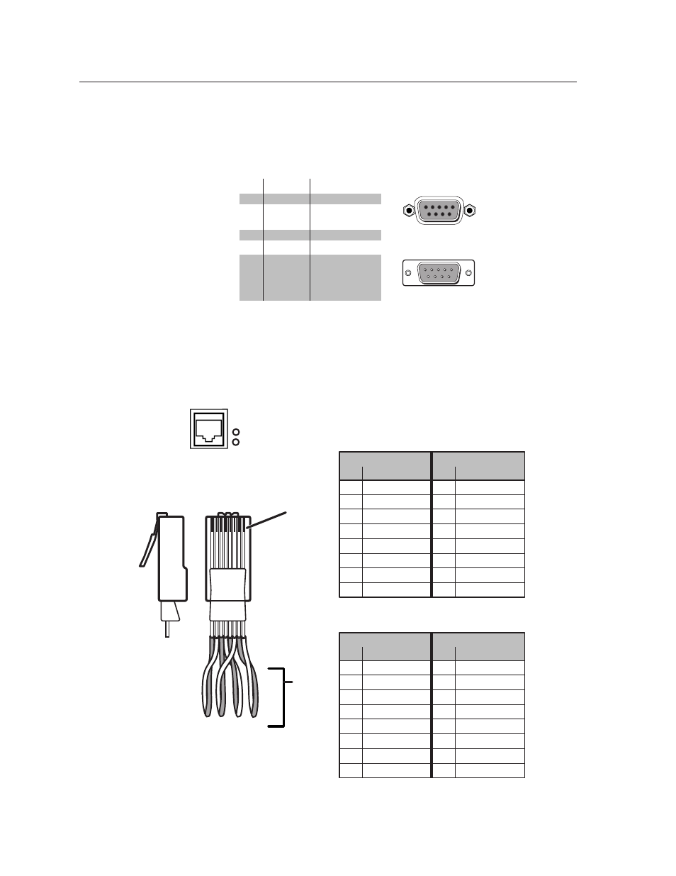
Ethernet Link
The rear panel Ethernet connector on the switcher can be connected to the an
Ethernet LAN or WAN. This connection makes SIS control of the
switcher possible using a computer connected to the same LAN or
WAN.
Clip Down
Side
1
1&2
3&6 4&5
7&8
2 3 4 5 6 7 8
1
Pins
2 3 4 5 6 7 8
RJ-45
connector
Patch (straight) cable
Twisted
Pairs
Side 1
Side 2
Pin
Wire color
Pin
Wire color
1
White-orange
1
White-orange
2
Orange
2
Orange
3
White-green
3
White-green
4
Blue
4
Blue
5
White-blue
5
White-blue
6
Green
6
Green
7
White-brown
7
White-brown
8
Brown
8
Brown
Crossover cable
Side 1
Side 2
Pin
Wire color
Pin
Wire color
1
White-orange
1
White-green
2
Orange
2
Green
3
White-green
3
White-orange
4
Blue
4
Blue
5
White-blue
5
White-blue
6
Green
6
Orange
7
White-brown
7
White-brown
8
Brown
8
Brown
Figure 4-2 — RJ-45 connector pinout table
ETHERNET
LINK
ACT