Pr eliminary pr eliminary, Maintenance and modifications, cont’d, Safety switch — location only – Extron Electronics HSA 822MS User’s Manual User Manual
Page 25
Maintenance and Modifications, cont’d
HSA 822MS • Maintenance and Modifications
HSA 822MS • Maintenance and Modifications
Pr
eliminary
Pr
eliminary
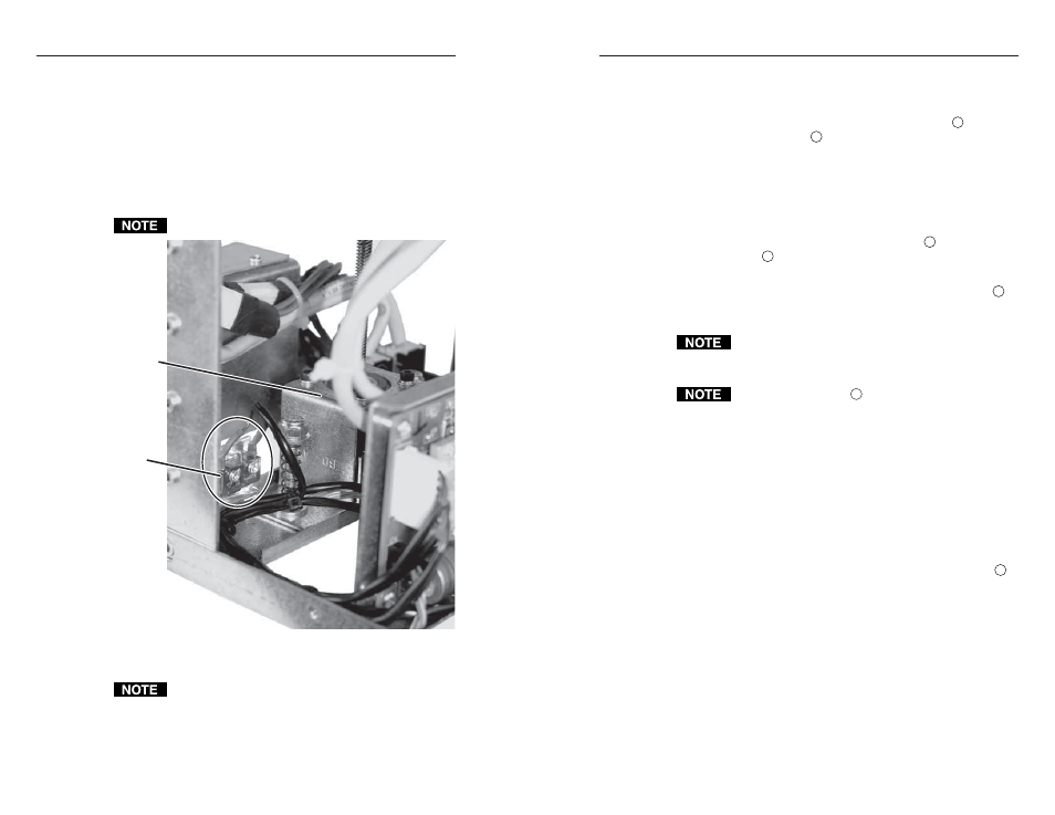
Safety Switch — Location only
The safety switch (figure 3-9) stops the downward motion of
platform when it encounters an obstruction to its smooth
operation. If an obstruction is present that blocks the platform’s
travel, the stepper motor’s carriage lifts and activates the safety
switch. The HSA’s motor logic automatically reverses the
platform’s motion and raises the platform to the upper position.
The carriage typically reverses with less than twelve pounds of
pressure applied to the obstruction.
Figure 3-9 shows the HSA with the shroud removed.
Safety
Switch
Stepper
Motor and
Carriage
Assembly
Figure 3-9 — Location of the safety switch
(seen from the side)
The safety switch cannot be adjusted.
Replacing the Control Board Assembly and
Power Supply Assembly
The control board assembly (figure 3-1 on page 3-2,
1
) and the
power supply assembly (
2
) can be replaced, if necessary, as
follows:
1
.
Disconnect AC power.
2
.
Remove the shroud. See Removing and Replacing the
Shroud, on page 3-6, step 1.
3
.
From the underside of the enclosure, reach into the cable
access holes (figure 3-1 on page 3-2, item
3
), and cut the
tie wraps (
5
shows the tie-downs) that route the AAP
cables and network (CAT 6) cables inside the enclosure.
4
.
Remove the three screws (figure 3-1 on page 3-2, item
4
)
that secure the assembly to be replaced to the underside of
the enclosure.
For the control board assembly, screws indicated by an
asterisk (*) on figure 3-1 are accessible from the top
(inside the enclosure).
Do not remove screw
X
(figure 3-1 on page 3-2).
This screw does not secure the power supply assembly in
any way; rather, it provides structural support to the
enclosure.
5
.
Remove all connectors from the assembly to be replaced.
6
.
Remove the assembly from the enclosure.
7
.
Secure the replacement assembly in the enclosure with the
screws removed in step 4.
8
.
Reconnect all connectors removed in step 5.
9
.
Retie all of the network (CAT 6) and AAP cables removed
in step 3 to the tie-downs (figure 3-1 on page 3-2, item
5
)
on the assembly that was replaced.
10
.
Reinstall the shroud. See Removing and Replacing the
Shroud, on page 3-6, step 3.
3-13
3-12