Pr eliminary pr eliminary, Installation, cont’d, Cabling the enclosure – Extron Electronics HSA 822MS User’s Manual User Manual
Page 16
HSA 822MS • Installation
HSA 822MS • Installation
Installation, cont’d
Pr
eliminary
Pr
eliminary
Cabling the Enclosure
Hardwired
(USA/domestic)
IEC
(International)
2
2
4
4
6
7
3
5
8
8
1
1
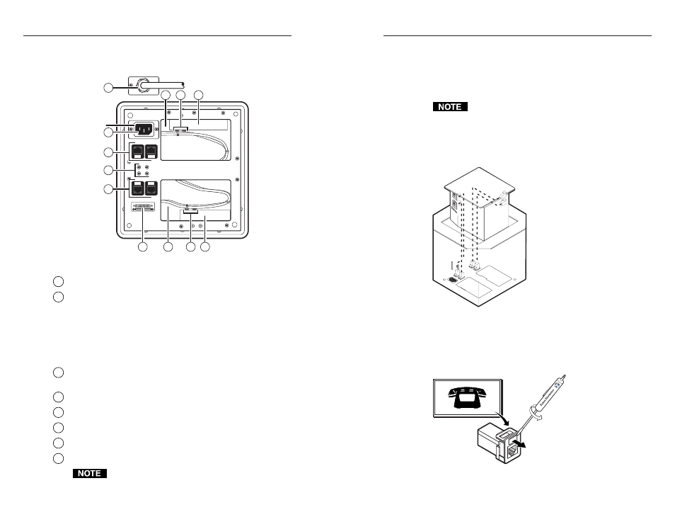
Figure 2-15 — HSA 822MS underside features
1
RJ-45 connectors
— See Cabling the RJ-45 connectors on page 2-19.
2
AC power connector
— Connect the enclosure to the
appropriate AC power source:
•
US domestic version —
125 VAC, 60 Hz, 5 A, using the
hardwired standard US power connector
•
International versions —
220-240 V, 50/60 Hz, 5 A, using
standard IEC power connector
3
Control and status captive screw connector
— See Cabling the
control and status connector on page 2-20.
4
Cable access holes*
5
Spare AAP/RJ-45 panel screws*
6
Power supply assembly*
7
Control board assembly*
8
Cable tie-downs*
Items marked with an asterisk (*) are concealed by the
removable tray.
Cabling the RJ-45 connectors
Plug one end of a terminated CAT 5 or CAT 6 twisted pair (TP)
cable into each of these RJ-45 female connectors. Connect the
other end to an appropriate telecommunications or data
network device or to an Extron TP product.
An RJ-11 (telephone) plug can be connected to the RJ-45
jack.
The bottom RJ-45 connectors match up with the AAP/RJ-45
panel RJ-45 connectors as shown in figure 2-16. For example,
match the AAP/RJ-45 panel RJ-45 connector A1 with the
underside RJ-45 connector A1, match A2 with A2, and so forth.
A1
A2
A1
A2
B1
B2
B1
B2
Figure 2-16 — HSA 822MS RJ-45 connectors
If necessary, have a qualified service person replace the
connector icon on the AAP/RJ-45 panel by prying the old icon
off of the connector plug-in with a Tweeker or small screwdriver
(see figure 2-17) and snapping a new icon in place.
Icon Labels
Figure 2-17 — Changing the connector icon
2-19
2-18
2-19