Pr eliminary pr eliminary, Maintenance and modifications, cont’d, Removing and replacing the shroud – Extron Electronics HSA 822MS User’s Manual User Manual
Page 22
Maintenance and Modifications, cont’d
HSA 822MS • Maintenance and Modifications
HSA 822MS • Maintenance and Modifications
Pr
eliminary
Pr
eliminary
5
.
Snap the interior RJ-45 cable
connectors onto the rear of the
replacement RJ-45 AAP panel
bezel plug-ins.
6
.
Replace the AAP/RJ-45 panel in
the surface mount enclosure and
secure it in place with the screws
removed in step 1. If you lose an
AAP/RJ-45 panel screw, four spare screws are stored in
the underside of the enclosure (figure 3-1 on page 3-2,
item
6
).
Removing and Replacing the Shroud
Many maintenance procedures require removing the protective
enclosure shroud from the HSA 822MS. Remove and replace
the shroud as follows:
1
.
Remove and retain the four screws in the corners of each
side’s surface of the enclosure shroud “cube” (figure 3-5).
Remove the two halves of the shroud.
HS
A 8
22M
S
HSA 822MS
Enclosure
Remove (4) Screws
(each side).
Figure 3-5 — Removing the shroud
You do not need to remove the screws in the center of two
of the sides. They do not secure the shroud in any way;
rather, they provide structural support to the enclosure.
2
.
Perform the desired maintenance procedure.
3-7
3-6
3
.
Secure the two shroud halves to the enclosure frame with
the eight screws per shroud half (four per side) removed in
step 1. Orient the shroud halves such that the vertical
column of center holes align with the column of screw
inserts on the vertical slides.
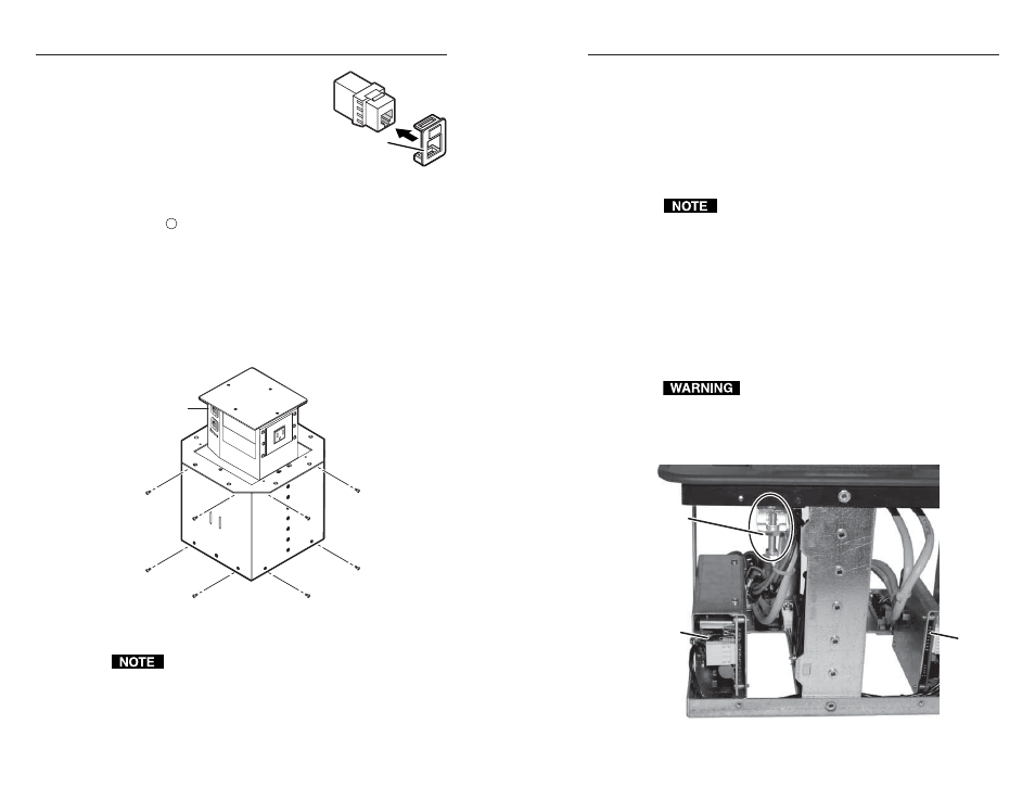
Setting the Upper Limit Switch
(Elevated Platform Height)
This switch’s position is properly set in the factory.
The upper limit switch sets the stop point for the raised
platform. If the switch is set too low, the platform does not rise
high enough. If the switch is set too high, the motor attempts to
raise the platform past the mechanical stop and then lowers the
platform to the recessed position. Set the platform’s height as
follows:
1
.
Remove the shroud. See Removing and Replacing the
Shroud, on page 3-6, step 1.
2
.
Activate the motor to raise the platform. Leave AC power
applied to the HSA.
Do not reach tools or your hands into the area
behind the AC connectors or into the vicinity of the
power supply.
3
.
Locate the upper limit switch assembly (figure 3-6) inside
the enclosure.
Upper Limit
Switch
Assembly
Power
Supply
Control
Board
Figure 3-6 — Location of upper limit switch assembly
(seen from the side)
RJ-45 Bezel
Plug-in in AAP
Panel