Pr eliminary pr eliminary, Maintenance and modifications, cont’d, Setting the manual release switch – Extron Electronics HSA 822MS User’s Manual User Manual
Page 24
Maintenance and Modifications, cont’d
HSA 822MS • Maintenance and Modifications
HSA 822MS • Maintenance and Modifications
Pr
eliminary
Pr
eliminary
3-10
Setting the Manual Release Switch
This switch’s position is properly set in the factory.
The manual release switch sets the amount of pressure needed
to activate the press-to-activate feature. If the switch is set too
low, you may have to push too hard on the platform. If the
switch is set too high, the drive mechanism may activate
sporadically. Set the height of the platform as follows:
It is unlikely that the position of the manual release
switch will ever need adjustment.
1
.
Remove the shroud. See Removing and Replacing the
Shroud, on page 3-6, step 1.
2
.
Activate the motor to raise the platform. Leave AC power
applied to the HSA.
Do not reach tools or your hands into the area
behind the AC connectors or into the vicinity of the
power supply.
3
.
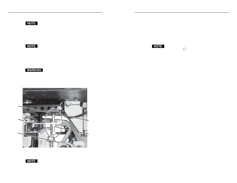
Locate the manual release switch assembly (figure 3-8)
inside the enclosure.
Manual
Release
Switch
Assembly
RJ-45
Connectors
Manual
Release
Switch
Manual
Release
Set Screw
Lower
Limit
Set Screw
Figure 3-8 — Location of manual release switch
assembly (seen from the side)
The manual release switch looks similar to, but not
exactly like the upper limit switch shown on page 3-8.
4
.
Loosen the manual release lock nut.
5
.
Rotate the manual set screw:
Clockwise
to make the manual release more sensitive.
Counterclockwise
to make the manual release less
sensitive (you must push harder to activate the press-to-
activate feature).
6
.
Press on the platform to activate the press-to-activate
function. If necessary, repeat step 5.
Pin 5 of the control and status connector (figure 3-1 on
page 3-2, item
9
) must be tied to ground to enable the
press-to-activate function.
7
.
Tighten the manual release lock nut.
8
.
Reinstall the shroud. See Removing and Replacing the
Shroud, on page 3-6, step 3.
3-11