Pr eliminary pr eliminary, Installation, cont’d, Bezels – Extron Electronics HSA 822MS User’s Manual User Manual
Page 18
HSA 822MS • Installation
HSA 822MS • Installation
Installation, cont’d
Pr
eliminary
Pr
eliminary
1
2
3
4
5
6
7
8
10
9
PWR SUP
+ -
Up
Do
wn
Stop
Enab
le
Up
status
Do
wn
status
Pwr
status
Figure 2-20 — Typical local control device
Figure 2-21 shows the HSA connected to an Extron MLC 226
MediaLink
™
Controller. The status pin can trigger the MLC’s
digital input.
CTL
BRD
V
2
1
+
1
W
S
HSA 822MS
S
U
T
A
T
S
NS
I
P
D
N
G
V
2
1
+
K
2
2
W
S
V
3
.
3
+
MLC 226
L
A
T
I
G
I
D
T
U
P
N
I
D
N
G
L
T
C
Figure 2-21 — Typical MediaLink control device
The MLC’s pull-up resistor to 3.3 VDC must be
activated (the MLC’s switch 2 closed). Refer to the
MLC 226 product manual.
The flex I/O port on an Extron IP Link
™
Ethernet
Control Interface can be used in place of the MLC 226
and its digital input port.
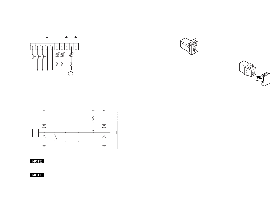
Bezels
The HSA 822MS ships with RJ-45/RJ-11 connector bezel plug-
ins in a variety of colors and a black, blank
bezel.
To change to a different color RJ-45 connector
bezel or if an RJ-45 connector is not needed or
desired, replace the connector bezel plug-in on
the AAP/RJ-45 panel with a bezel of a different
color or a blank plug-in. See Replacing the Bezels
in chapter 3.
If no RJ-45 connector is desired, snap
the interior RJ-45 cable onto the rear of
the blank bezel plug-in (shown at
right) to hold it conveniently out of the
way. Retain the removed connector
bezel plug-in for any possible later
use.
Bezel
Blank Bezel
Plug-in in AAP
Panel
2-23
2-22