Pr eliminary pr eliminary, Maintenance and modifications, cont’d – Extron Electronics HSA 822MS User’s Manual User Manual
Page 23
Maintenance and Modifications, cont’d
HSA 822MS • Maintenance and Modifications
HSA 822MS • Maintenance and Modifications
Pr
eliminary
Pr
eliminary
Upper Limit
Switch
(Hidden)
Switch
Actuator
Upper Limit
Lock Nut
Upper Limit
Set Screw
4
.
Loosen the upper limit
lock nut.
5
.
Rotate the upper limit
set screw:
Clockwise
to lower
the upper limit of
platform motion.
Counterclockwise
to raise
the upper limit of platform
motion.
Adjustments do not take affect immediately. You must
use the motor mechanism to lower and raise the platform
to see the affect of your adjustment.
6
.
Lower and raise the platform to check the adjusted height.
If necessary, repeat step 5.
7
.
Tighten the upper limit lock nut.
8
.
Reinstall the shroud. See Removing and Replacing the
Shroud, on page 3-6, step 3.
Setting the Lower Limit Switch
(Lowered Platform Height)
This switch’s position is properly set during the
installation.
The lower limit switch sets the stop point for the lowered
platform. If the switch is set too high or low, the retracted
platform is not flush with the surrounding flange. Set the
retracted height of the platform as follows:
1
.
Disconnect AC power.
2
.
Remove the shroud. See Removing and Replacing the
Shroud, on page 3-6, step 1.
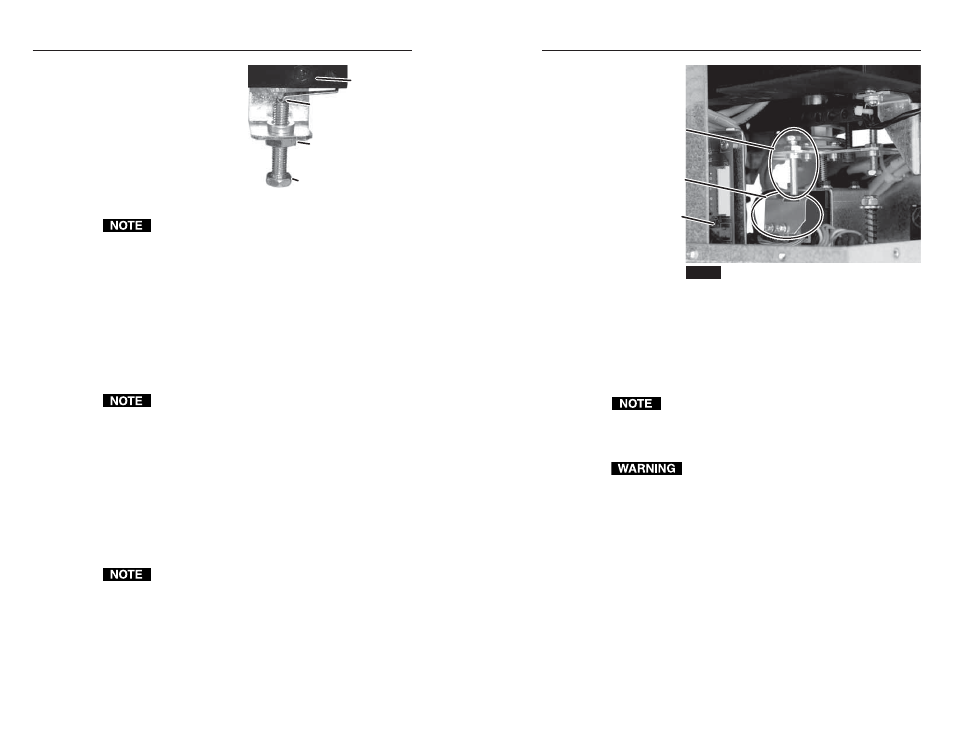
3
.
Locate the lower limit switch assembly (figure 3-7) inside
the enclosure. Loosen the lower limit lock nut.
The lower limit switch looks similar to, but not exactly
like the upper limit switch shown on page 3-8.
3-9
3-8
Lower Limit
Set Screw
Control
Board
NOTE
RJ-45 connectors are removed for visibility.
Lower Limit
Switch
Figure 3-7 — Location of lower limit switch assembly
(seen from the side)
4
.
Rotate the lower limit set screw:
Clockwise
to raise the stop point of the retracted platform.
Counterclockwise
to lower the stop point of the retracted
platform.
Adjustments do not take affect immediately. You must
use the motor mechanism to raise and lower the platform
to see the affect of your adjustment.
5
.
Plug in AC power.
Do not reach tools or your hands into the area
behind the AC connectors or into the vicinity of the
power supply.
6
.
Raise and lower the platform to check the adjusted height.
If necessary, repeat step 1 and then step 4.
7
.
Tighten the lower limit lock nut.
8
.
Reinstall the shroud. See Removing and Replacing the
Shroud, on page 3-6, step 3.