Pr eliminary pr eliminary, Installation, cont’d – Extron Electronics HSA 822MS User’s Manual User Manual
Page 17
HSA 822MS • Installation
HSA 822MS • Installation
Installation, cont’d
Pr
eliminary
Pr
eliminary
Cabling the control and status connector
Plug one end of the control cable(s) into this 10-pole captive
screw connector. Connect the other end of the cable(s) to a
control and/or monitoring system. The following table
identifies the signals on each pin of the connector.
Control and status connector pinout
1
2
3
4
5
6
7
8
9
10
Up (control)
Down (control)
Stop (control)
Gnd
Enable
Up (status)
Down (status)
Gnd
Power (status)
Gnd
Momentary
contact closure
Momentary
contact closure
Momentary
contact closure
Gnd
Contact closure
Grounded/
open
Grounded/
open
Gnd
Grounded/
open
Gnd
Short to ground to raise
(open) the top panel.
Short to ground to lower
(shut) the top panel.
Short to ground to stop
the top panel's motion.
Ground
Short to ground to enable
activating the motor by
pressing on the top panel.
Grounded = up
Open = down or in motion
Grounded = down
Open = up or in motion
Ground
Grounded = AC power is
applied.
Open = No power is
applied.
Ground
Pin Definition
Definition
Explanation
1
2
3
4
5
6
7
8
10
9
Up
Do
wn
Stop
Enab
le
Up
status
Do
wn
status
Pwr
status
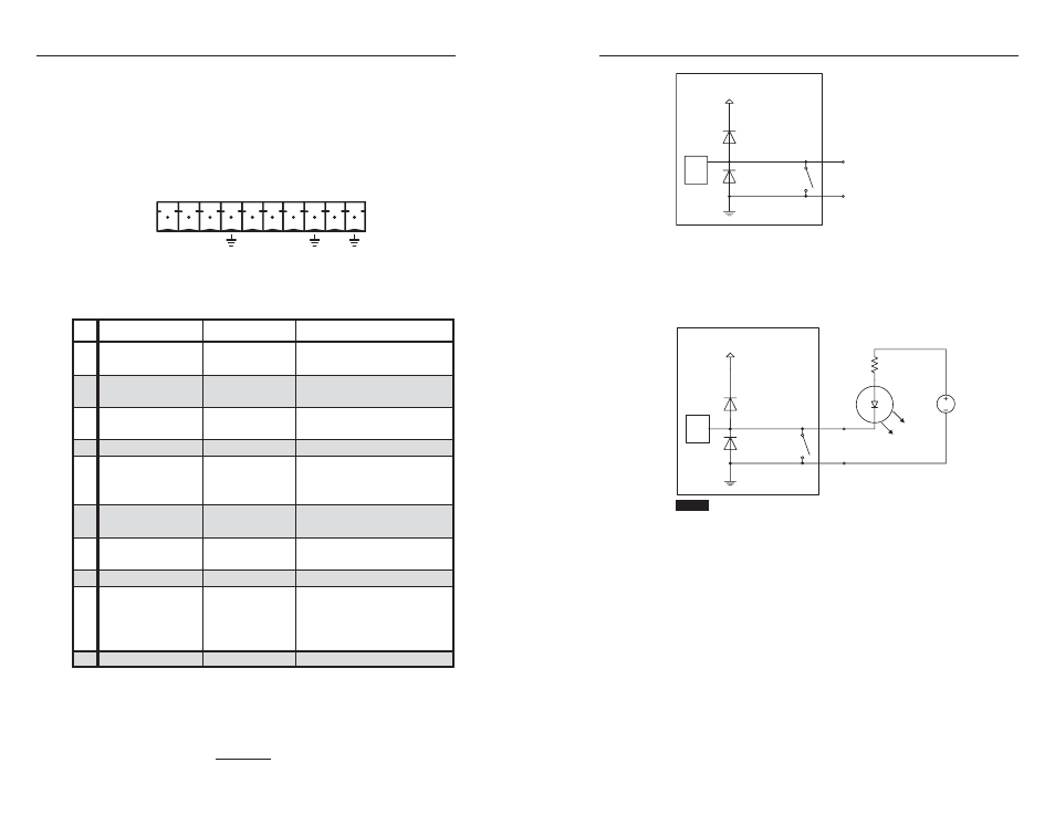
Figure 2-18 shows the function of the HSA’s status pins (6 [up],
7 [down], and 9 [power]). When a status condition is met, the
switch closes, shorting the status pin to ground, pulling it low.
When a status condition is not met, the switch opens, floating
the status pin. Status pins 6, 7, and 9 can sink +5 VDC to
+12 VDC
, 500 mA, maximum.
V
2
1
+
1
W
S
STATUS
PIN
D
N
G
HSA 822MS
CTL
BRD
Figure 2-18 — Equivalent status pin circuit
Figure 2-19 expands upon figure 2-18 to show suggested
circuitry to display the HSA’s status. In this figure, the LED
lights for as long as the status pin is pulled low (the switch is
shorted [closed]).
STATUS
PINS
470
HSA 822MS
NOTE
This drawing shows a standard +5 V power supply. +12 V is another
standard power supply that can be used in this circuit. If you use a
+12 V supply, use a 2k ohm resistor in place of the 470 ohm resistor shown.
CTL
BRD
V
2
1
+
1
W
S
D
N
G
D
E
L
V
5
+
T
X
E
C
R
S
Figure 2-19 — Typical status display circuit
If connected to a position (up or down) status pin, the LED
lights when the HSA platform is in the stated position. The LED
is unlit when the platform is in motion or in the opposite
position. Under no circumstances should both position LEDs
light simultaneously.
If connected to the power status pin, the LED is lit when as
power is applied to the HSA.
Figure 2-20 shows a typical locally-constructed contact closure
control and LED indication device.
2-21
2-20