Pr eliminary pr eliminary, Maintenance and modifications, Replacing an aap – Extron Electronics HSA 822MS User’s Manual User Manual
Page 20: Hsa 822 co mpu ter inp ut sel ect au dio
Maintenance and Modifications
HSA 822MS • Maintenance and Modifications
HSA 822MS • Maintenance and Modifications
Pr
eliminary
Pr
eliminary
3-2
CAUTION
Installation and service must be performed by
authorized personnel only.
This chapter provides the following procedures:
Maintenance procedures marked with an asterisk (*)
require removing the shroud from the HSA 822MS.
•
Replacing an AAP
•
Replacing the bezels
•
Removing and replacing the HSA shroud (in advance of
other maintenance procedures)*
•
Adjusting the upper-level and lower-level stop point and
the manual mode release point*
•
Replacing the power supply assembly and the control
board assembly*
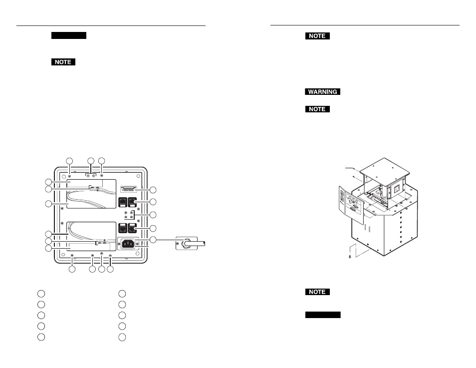
Figure 3-1 shows the underside of the enclosure (with the tray
removed) and many of the maintenance-related features.
Hardwired
(USA/domestic)
IEC
(International)
4
4
X
X=Do not remove.
X
4
4
3
1
3
2
5
5
4
6
9
8
8
7
✝
Figure 3-1 — HSA 822MS maintenance features
1
Control board assembly
6
Spare AAP/RJ-45 panel screws
2
Power supply assembly
7
AC power connector
3
Cable access holes
8
RJ-45 connector
4
Assembly screws
✝
9
Control and status connector
5
Cable tie-downs
X
Structural screws —
Do not remove.
The screws indicated by a dagger (
✝
) on figure 3-1 are
accessible from the top (inside the enclosure).
Replacing an AAP
Replace one or more AAPs as follows:
1
.
Activate the motor to raise the platform, and then
disconnect the AC power.
Ensure that AC power is disconnected before
servicing the HSA unit.
When AC power is removed, the platform may sink
partially down into the HSA.
2
.
Remove and retain the top and bottom screws on the right
and left sides of the AAP/RJ-45 panel (figure 3-2). Lift the
panel away from the enclosure as far as the connected
cables allow and then allow the panel to dangle,
supported by its connected cables.
Remove panel.
Remove two
screws ea. side.
HSA
822
CO
MPU
TER
INP
UT
SEL
ECT
AU
DIO
Replacement Face Plate
Screws (4) under Enclosure
Figure 3-2 — Removing the AAP/RJ-45 panel
The center screws on each side of the AAP/RJ-45 panel
do not fasten the AAP/RJ-45 panel in place. They secure
the AC power outlet.
CAUTION
Ensure that the edges of the AAP/RJ-45 panels do
not scratch the finished surface of the top panel
flange or the furniture in which the HSA 822MS is
installed when removing the panels.
3-3