Pr eliminary pr eliminary – Extron Electronics HSA 822MS User’s Manual User Manual
Page 10
HSA 822MS • Installation
HSA 822MS • Installation
Installation, cont’d
Pr
eliminary
Pr
eliminary
2-6
3
.
Remove and retain the four screws in the corners of each
side’s surface of the enclosure shroud “cube” (figure 2-4).
Remove the two halves of the shroud and set them aside.
HS
A 8
22M
S
HSA 822MS
Enclosure
Remove (4) Screws
(each side).
Figure 2-4 — Removing the shroud
You do not need to remove the screws in the center of two
of the sides. They do not secure the shroud in any way;
rather, they provide structural support to the enclosure.
4
.
Manually raise the top surface.
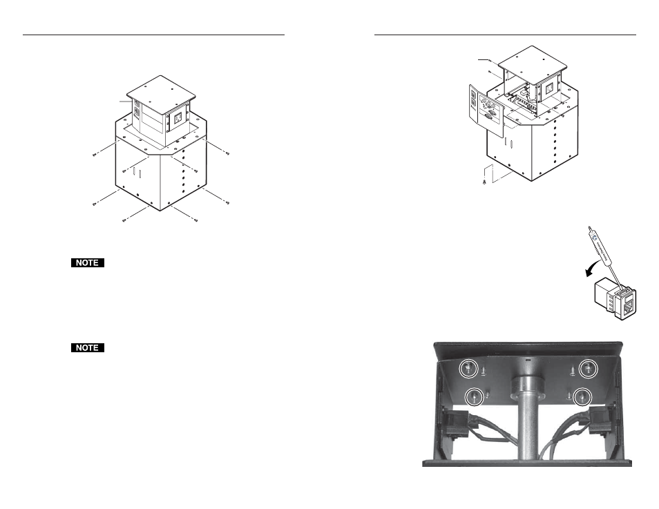
5
.
For both AAP/RJ-45 panels, remove the top and bottom
screws on the right and left sides of the panel (figure 2-5).
Retain the screws. Lift the panels away from the enclosure
as far as the connected cables allow.
The center screws on each side of the panel do not fasten
the panel in place. They secure the AC power outlet.
6
.
To ensure that you reinstall the RJ-45 connectors in the
proper position when the installation is complete, tag the
internal CAT 6 cables to define their installation location
(such as top or bottom and side A or B).
Also tag the side of the enclosure itself (A or B).
Remove panel.
Remove two
screws ea. side.
HSA
822
CO
MPU
TER
INP
UT
SEL
ECT
AU
DIO
Replacement Face Plate
Screws (4) under Enclosure
Figure 2-5 — Removing the AAP/RJ-45 panel
7
.
With a Tweeker, inside the AAP/RJ-45
panels, push down on and gently twist on
the front of each RJ-45 connector detent to
disconnect the connector from the rear of
the AAP/RJ-45 panel plug-in.
8
.
Disconnect any cables from the rear of the
existing AAPs.
9
.
Set the AAP/RJ-45 panels aside.
10
.
Remove and retain the four 1/4" nuts that
secure the top plate to the lifting plate
(figure 2-6). Set the plate aside.
Figure 2-6 — Location of the top plate nuts
2-7