Bell & Gossett S13641B Technologic 5500 Series Pump Controller User Manual
Page 26
26
4.4.2
Remote Automatic Operation
With the LOCAL-REMOTE-OFF (L-R-O) switch in the
REMOTE position check that the LED indicators on
the Operator Interface Panel (OIP) are as follows:
LED
Condition
Meaning
Start/Stop
Flashing Green
System is stopped.
No pumps running.
Pump 1 On/Off
Flashing Green
Pump1 is enabled
but not on.
Pump 2 On/Off
Flashing Green
Pump2 is enabled
but not on.
If a pump is not running this means the start contact
(from the energy management system or other
source) is not closed and the controller has not been
given a start signal.
Once operating in remote it is possible to stop opera-
tion (i.e., override the remote start command) by
either turning the L-R-O switch to off or by pressing
the START/STOP key on the OIP. It is recommended
to TURN THE L-R-O SWITCH TO OFF to stop the
system if it is running in remote.
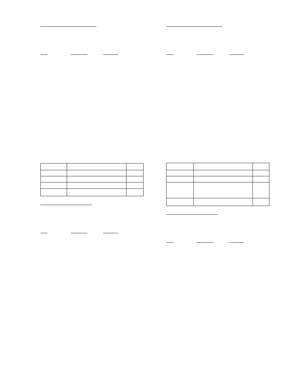
4.5
C0 OPERATION
Confirm the setup of the following items:
Section
Item
Value
3.5.3
Total # of pumps
2
3.7.1
PV stage speed %
0
3.7.1
EOC pump max. flow
0
3.11.1
Number of pumps in bypass
0
4.5.1
Local Automatic Operation
With the LOCAL-REMOTE-OFF (L-R-O) switch in the
LOCAL position check that the LED indicators on the
Operator Interface Panel (OIP) are as follows:
LED
Condition
Meaning
Start/Stop
Flashing Green
System is stopped.
No pumps running.
Pump 1 On/Off
Flashing Green
Pump1 is enabled
but not on.
Pump 2 On/Off
Flashing Green
Pump2 is enabled
but not on.
Take note of the pump sequence. Only the first pump
in the sequence will run in normal operation. The sec-
ond pump is a standby and will run only if the duty
fails. To change which pump is the duty pump press
the ALTERNATION/4 key.
Press the START/STOP key. The flashing green LED
will turn solid green. After a brief delay the duty pump
LED will turn solid green indicating that it is running
variable speed. It will then try to maintain setpoint by
varying pump speed.
4.5.2
Remote Automatic Operation
With the Local-Off-Remote (L-R-O) switch in the
REMOTE position check that the LED indicators on
the Operator Interface Panel (OIP) are as follows:
LED
Condition
Meaning
Start/Stop
Flashing Green
System is stopped.
No pumps running.
Pump 1 On/Off
Flashing Green
Pump1 is enabled
but not on.
Pump 2 On/Off
Flashing Green
Pump2 is enabled
but not on.
If a pump is not running this means the start contact
(from the energy management system or other
source) is not closed and the controller has not been
given a start signal.
Once operating in remote it is possible to stop opera-
tion (i.e., override the remote start command) by
either turning the L-R-O switch to off or by pressing
the START/STOP key on the OIP. It is recommended
to TURN THE L-R-O SWITCH TO OFF to stop the
system if it is running in remote.
4.6
D0 OPERATION
Confirm the setup of the following items:
Section
Item
Value
3.5.3
Total # of pumps
2
3.7.1
PV stage speed %
95%
3.7.1
EOC pump max. flow
max.
pump
flow
3.11.1
Number of pumps in bypass
0
4.6.1
Local Automatic Operation
With the LOCAL-REMOTE-OFF (L-R-O) switch in the
LOCAL position check that the LED indicators on the
Operator Interface Panel (OIP) are as follows:
LED
Condition
Meaning
Start/Stop
Flashing Green
System is stopped.
No pumps running.
Pump 1 On/Off
Flashing Green
Pump1 is enabled
but not on.
Pump 2 On/Off
Flashing Green
Pump2 is enabled
but not on.
Take note of the pump sequence. The first pump in
the sequence will be the lead pump. The other pump
will stage on if it is needed to maintain setpoint. To
change which pump is the lead pump press the
ALTERNATION/4 key.
Press the START/STOP key. The flashing green LED
will turn solid green and the message STARTUP-
STANDBY will be displayed. After a brief delay the
lead pump LED will turn solid green indicating that it
is running variable speed. It will then try to maintain
setpoint by varying pump speed. The lag pump will
stage on if required.