Bell & Gossett S13641B Technologic 5500 Series Pump Controller User Manual
Page 24
24
3.23.2
Press the F1/5 key at the Setup Selection menu.
Then press the ENTER key.
3.23.3
The display will show:
*WARNING*
ALL SETUP DATA WILL BE OVER WRITTEN.
PROCEED: ? (Y/N)
Press the NO/0 key to exit the default setup menu
and save all current factory/field variables. Press the
YES/7 key to load all of the pre-defined default vari-
ables. Once the variables are loaded the controller
will return to the display screen that was present prior
to entering the setup menu.
3.23.4
After setting the default values proceed with complet-
ing the system setup per Sections 3.4 to 3.18.
Section 4 - Operation
4.0
TYPE OF PROGRAM
There are nine operational programs with the
Technologic 5500 family of controls. Refer to the
nameplate on the front of the controller to determine
which program has been furnished.
B&G
No. of
Bypass
Program
Pumps Provided
Description
A0
1
No
One Pump/One AFD
A1
1
Yes
One Pump/One AFD
Constant speed or variable
speed operation
B3
2
Yes
Two Pumps/One AFD
Either pump operating
constant speed or variable
speed.
C0
2
No
Two Pumps/Two AFDs
Two 100% duty pumps and
AFDs without staging.
D0
2
No
Two Pumps and AFDs
Both pumps may stage and
run variable speed.
D4
2
Yes
Two Pumps and AFDs
Both pumps may stage
and run variable speed
or constant speed.
NOTE: Constant Speed refers to across-the-line operation.
4.0.1
Normal Scrolling Operation
Other screens may be viewed by scrolling from the
Technologic Pump Controller screen shown below:
TECHNOLOGIC
PUMP CONTROLLER
MM/DD/YY HH:MM:SS
STATUS MODE
The status portion of the display indicates the current
alarm status. If NORMAL is displayed there are no
alarms. If *ALARM* is displayed there are alarms that
may prevent normal operation, refer to Section 4.15
for additional information.
The mode portion of the display indicates the current
auto/manual mode of operation. The following table
indicates all possible options:
Sections for
Additional
Mode
Description
Infomation
AUTO
Pump Controlled by
4.1 - 4.7
Controller
MANUAL
Variable Speed Pumps
4.11
Controlled by User
MAN. BPS
Constant Speed Pumps
4.10
Controlled by User
4.0.2
Press the NEXT SCREEN key.
The display now shows:
PUMP STATUS
P1:(RDY or N/A)P2: (RDY or N/A) P3:(RDY or N/A)
P4:(RDY or N/A)P5: (RDY or N/A) P6:(RDY or N/A)
STATUS
MODE
Press the NEXT SCREEN key.
The display now shows:
ACTIVE VALUES
Zone: ##
Speed: ###%
Seq: #
STATUS
MODE
Press the NEXT SCREEN key.
The display now shows the following if any of the
transmitters are set up:
FLOW RATE: #### GPM
TOTAL KW: ###
SYS DP: ##
EFF: ## %
STATUS
MODE
Press the NEXT SCREEN key.
The display now returns to the Technologic Pump
Controller screen.
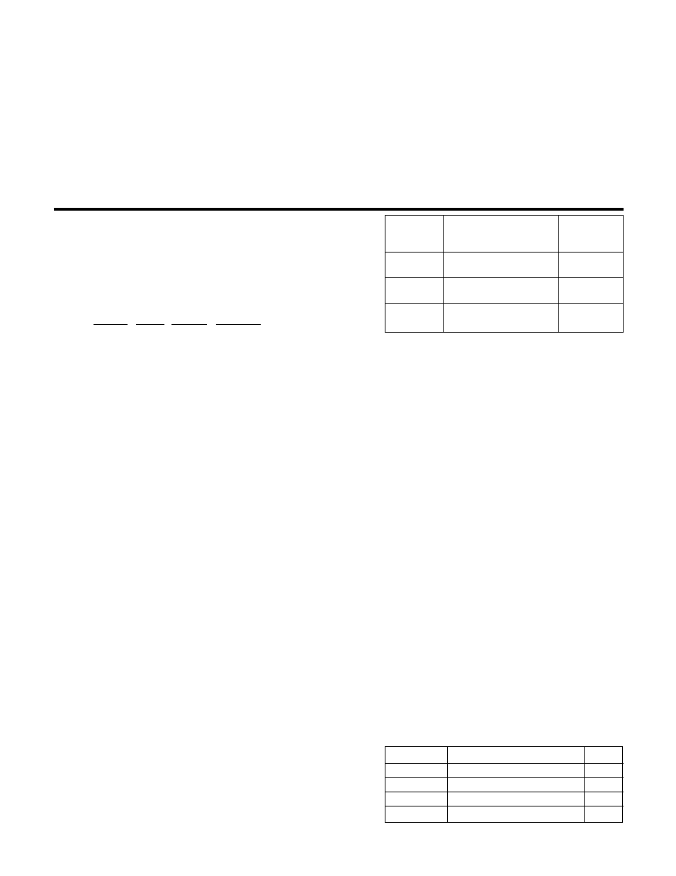
4.1
A0 OPERATION
Confirm the setup of the following items:
Section
Item
Value
3.5.3
Total # of pumps
1
3.7.1
PV stage speed %
0
3.7.1
EOC pump max. flow
0
3.11.1
Number of pumps in bypass
0