Bell & Gossett S13641B Technologic 5500 Series Pump Controller User Manual
Page 18
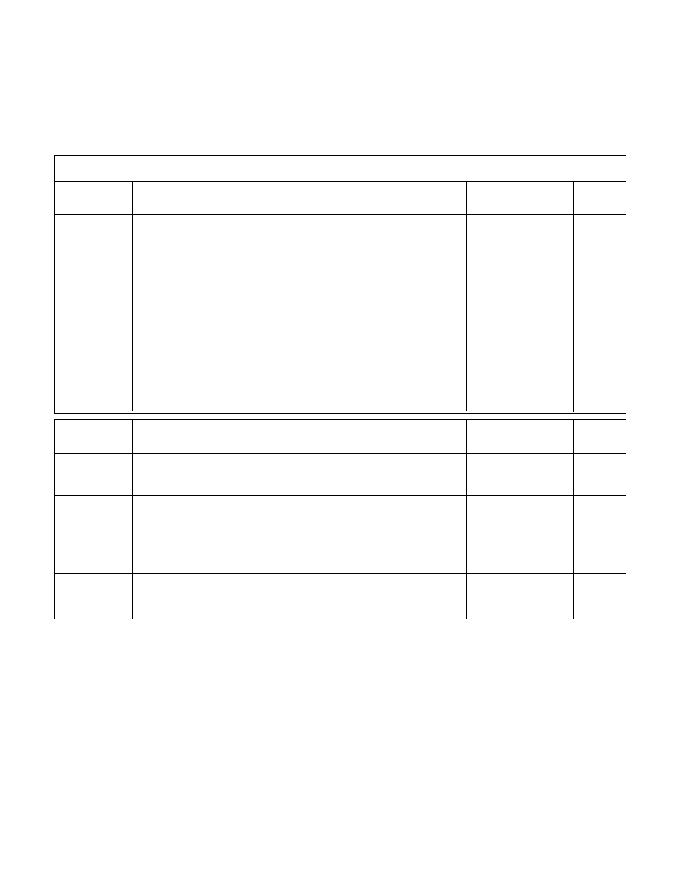
I/O MENU ITEMS
Field
Menu Item
Variable
Default
Range
Value
DI
Opt. DI ####
N/A
0-9999
Enter the input to be configured as it appears on the digital
input module. The first digit is the rack number. The second digit
is the slot number. The third and fourth digits are the input numbers.
For example, a digital input configured on rack 0, slot 0, input 1
would be encoded as 0001
DI
Avail: ##
N/A
0-99
This screen can not be modified. It is here to advise the user of
how many digital inputs can be customized
DI
* Code: ###
0
0-255
Enter the code to define the desired functionality of the input.
Valid codes are defined in the Appendix C of this manual.
DI
Delay: ###s
0
0-999
Enter the proof timer in seconds.
18
Field
Menu Item
Variable
Default
Range
Value
DO
Total Avail. DO = O
N/A
0-99
This screen can not be modified. It is here to advise the user of
how many digital outputs can be customized
DO
* DO No: ####
N/A
0-9999
Enter the output to be configured as it appears on the digital
output module. The first digit is the rack number. The second digit
is the slot number. The third and fourth digits are the input numbers.
For example, a digital output configured on rack 2, slot 1, input 1
would be encoded as 2101
DO
* Code: ###
0
0-255
Enter the code to define the desired functionality of the output.
Valid codes are defined in the Appendix C of this manual.
3.15
I/O SETUP
3.15.1
See the following table for all I/O menu items.
NOTE: The total available number of I/O to be config-
ured is dependent on the system setup. Complete all
previous setup screens, specifically pumps and sen-
sors prior to completing the following.