3 layout of control pcb inside control box, Fig. 53 control box inside (w/o sel unit), Fig. 54 control box inside (with sel unit) – GE Industrial Solutions GERAPID 2607, 4207, 6007, 8007 with arc chutes 1X2, 1X4, 2X2, 2X3, 2X4 User Manual
Page 46: 4 replacement of the control boards, Fig. 55-2 unscrew four bolts of the box cover, Fig. 55-3 carefully lower the box cover
46
Design and specifications are subject to change without notice
S47183e rev.03 2010-06-07
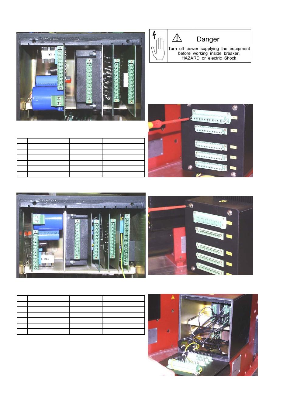
6.2.3 Layout of control PCB inside control box
Fig. 53 Control box inside (w/o SEL unit)
Slot Control board
Z-No.
Orientation
1
-
-
-
2
NEKO unit (ED trip)
128 750 R1
equipment to left
3
Voltage converter
128 730 R2-R4 equipment to left
4
SU-control unit
128 700
equipment to right
5
-
-
-
6
ST/UVR control unit
128 710 R1, R2
equipment to left
Table 5 Layout of control PCBs inside the box w/o SEL
Fig. 54 Control box inside (with SEL unit)
Slot Control board
Z-No.
Orientation
1
NEKO unit (ED trip)
128 750 R1
equipment to right
2
Voltage converter
128 730 R2-R4 equipment to right
3
SU-control unit
128 700
equipment to left
4
ST/UVR control unit
128 710 R1, R2
equipment to right
5
-
-
-
6
SEL control unit
128 785 R1-R2
equipment to left
Table 6 Layout of control PCBs inside the box with SEL
•
Warning: The isolation plates between the control
boards and at the wall of the box must always be
present!
•
Hint: In older systems, the control boards may be
installed turned 180 °!
6.2.4 Replacement of the control boards
1. OPEN the breaker.
2. Disconnect power supply, and pull out all
the plugs from control box’s terminals.
3. If a NEKO control unit is installed, wait 1
minute until capacitors discharge.
Fig. 55-1 Unscrew and remove all the external plugs
Fig. 55-2 Unscrew four bolts of the box cover
Fig. 55-3 Carefully lower the box cover
Slot numbers:
1
2
3 4 5 6
Slot numbers:
1
2
3 4 5 6