3 electrical diagrams, 1 wiring code, Fig. 22 example code shown on the nameplate – GE Industrial Solutions GERAPID 2607, 4207, 6007, 8007 with arc chutes 1X2, 1X4, 2X2, 2X3, 2X4 User Manual
Page 17: Indication of components
2010-06-07 S47183e rev.03
Design and specifications are subject to change without notice
17
4.3 Electrical diagrams
4.3.1 Wiring code
•
The main circuits are not shown in the wiring diagrams
for transparency. The control circuit is presented as a
typical circuit diagram and is a combination of numbered
basic diagrams for drives, trips and indicators.
•
Using the key numbers of the basic plan, you can derive
the number of the complete diagram.
•
WARNING: Some non standard electrical circuits do not
comply with the diagrams in this instruction. Such circuits
are coded with unique numbers i.e 36/0033. In such a
case an appendix to this instruction is delivered, which
contains relevant electrical diagrams.
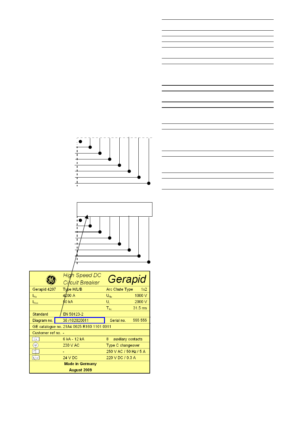
Coding positions:
Key position:
1
/ 2 3 4 5 6 7 8
Breaker type
Aux. voltage supply
ED impulse release
Closing drive
Aux. tripping device
Indicators
Aux. switches
SEL system
EXAMPLE:
Key number:
36 / 1
0 20 20 01
1
Gerapid
With voltage converter
Without ED and NEKO
With closing drive
With UVR release
With OCT trip target
With 3 aux. switches
Without SEL system
Fig. 22 Example code shown on the nameplate.
Key
position
Key
number
Designation
Type
1 36 Gerapid
Auxiliary voltage
2 1 Voltage
converter
2
DC 24 V external supply
Tripping coil
3 0 Without
ed-trip
coil
1
With ed-trip coil
2
With ed-trip coil and NEKO
control unit
Drive
4
20
Solenoid drive with
SU control unit
Tripping device
5 00 Without
trip
unit
10
With
shunt
trip
20
With zero voltage release
Indication device
6 00 Without
indicators
01
OCT trip target
02
Arc chute indicator
03
OCT + arc chute indicator
Auxiliary contacts
7
1
3 auxiliary contacts
2
5 auxiliary contacts
3
10 auxiliary contacts
Current-measurement system
8 S with
SEL
Indication of components
Q1
Impulse ED coil
Q2
Closing drive coil
S1 Push
button
„CLOSE“
S2
Push button „OPEN“, type NO
S3
Push button “OPEN”, type NC
SU control PCB:
K1 Closing
relay
K2
Internal closing stop relay
1)
Shunt trip, zero voltage release PCB:
K1
Internal closing stop relay
1)
K2 Tripping
relay
HS11
Shunt trip self cut-off auxiliary contact
ED-tripping device with internal NEKO PCB:
K1
Voltage monitoring relay
K2
Internal closing stop relay
1)
1)
These relays are part of internal closing stop circuit.
It is a 24 V DC closed circuit, through all PCBs in the box,
except SEL. Serial connection of all relays is realized
through connections ( :5/:6) in each PCB. This circuit
provides priority of a tripping signal over a closing signal.
Additionally it prevents from closing the internal supply
24 V DC lost at UVR PCB or NEKO PCB.