12 current measurement system (code 6), Fig. 17 sel current measurement system, 13 electronic control system – GE Industrial Solutions GERAPID 2607, 4207, 6007, 8007 with arc chutes 1X2, 1X4, 2X2, 2X3, 2X4 User Manual
Page 11: Fig. 18 control box with control units, Fig. 19-1 neko control unit, Fig. 19-2 voltage converter 110 v/24 v dc
2010-06-07 S47183e rev.03
Design and specifications are subject to change without notice
11
3.2.12 Current measurement system (Code 6)
•
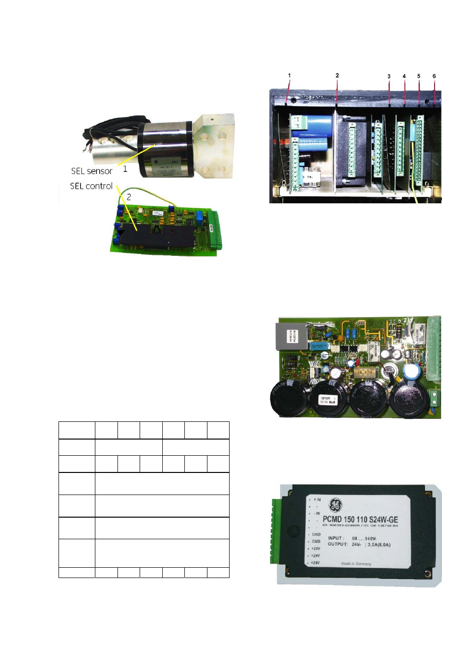
The SEL current measurement system consists of the
sensing component (1) and signal-processing unit (2)
[Fig.17]. SEL sensor is integrated into a specially shaped
upper terminal of the breaker and is connected by a
shielded cable to the signal-processing unit. SEL control
unit is placed in the control-box [Fig. 18].
Fig. 17 SEL current measurement system
•
SEL may be used for recording DC currents in selected
measurement ranges of 6 kA or 12 kA. Measurement of
rated current values and of the current rise may now be
made directly at the breaker.
•
The sensor includes Hall-probes and delivers a
proportional signal-output to the SEL control. The signal-
processing unit transforms input signal, into standard
output signals shown in the table below.
•
The outputs are insulated from the main voltage. The
insulation withstands voltages up to 4 kV RMS and up to
40 kV in peak.
•
Two versions are available. Standard model (T35) for
ambient temperature –5 °C…+35 °C and the model for
higher temperature (T55) –5 °C…+55 °C.
•
More details can be found in separate instruction for SEL
usage.
Type
SEL 06-1 06-2 06-4 12-1 12-2 12-4
Input
- 6 kA…+6 kA
-12 kA…+12 kA
U
Ne
[V]
1000 2000 4000 1000 2000 4000
T35
for ambient temperature of the breaker
-5 °C…+35 °C / +23 °F…+95 °F
T55
for ambient temperature of the breaker
-5 °C…+55 °C / +23 °F...+131 °F
I
Ne
Relating to the rated current of the breaker
Output 4...20
mA
-20...20 mA
-10...10 V
U
Ni
[kV] 12 18 40 12 18 40
3.2.13 Electronic control system
All the control PCBs are installed in control box [Fig. 18].
Starting from the left, these are:
Fig. 18 Control box with control units
•
(1) NEKO control unit [Fig. 19-1] (Code 12) – internal
control unit with capacitor bank. Releases firing signal for
ED coil (-X2 :10/:11) and provides indication of the
capacitors charging (-X3 :6/:7). NEKO control unit also
blocks the firing signal until C-bank is fully charged
(~15 sec).
•
WARNING: NEKO unit requires a high quality firing signal.
Be sure, that voltage level is between 6 V…24 V DC and
there are no short spikes on signal (<3 ms). This might
lead to major defect of the NEKO control unit!
Fig. 19-1 NEKO control unit
•
(2) Internal voltage converter (Code 8) - converts
external supply voltage (-X3 :4/:5) to the internal
24 V DC. Required by controls (except for the drive
supply).
Fig. 19-2 Voltage converter 110 V/24 V DC.