GE Industrial Solutions GERAPID 2607, 4207, 6007, 8007 with arc chutes 1X2, 1X4, 2X2, 2X3, 2X4 User Manual
Page 14
14
Design and specifications are subject to change without notice
S47183e rev.03 2010-06-07
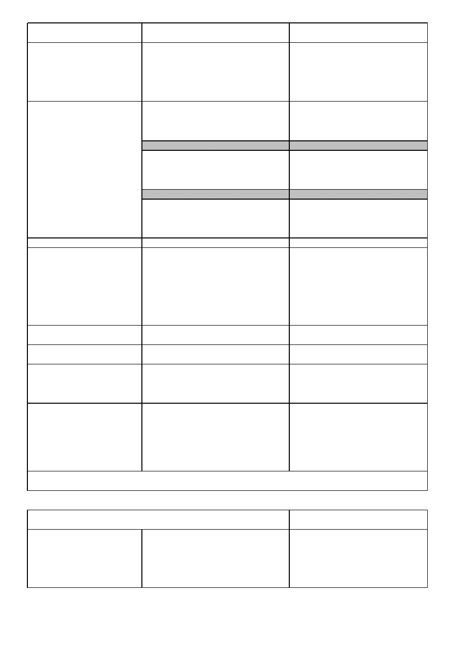
Control box terminals
1x12-pole
AC 400 V, 20 A
4x15-pole
AC 250 V, 8 A
Closing solenoid drive
1)
Rated voltage
AC 48 V - 230 V and DC 48 V - 220 V
Operating range
80 % - 115 % of rated voltage
Power consumption Gerapid 2607 / 4207
1750 W / 2000 W
Power consumption Gerapid 6007 / 8007
2600 W / 2600 W
Minimal CLOSING command duration
100 ms
min.interval between two "CLOSE" operations
~8 s w/o NEKO installed; ~14 s with NEKO
Internal voltage converter
1)
Input: Voltage range
DC 33 - 85 V
for Gerapid 2607, 4207, 6007, 8007
Output: Voltage range
DC 24 V (±5%)
Current
6 A permanent
Model description
PCMD 150 48 S24W-GE
Input: Voltage range
DC 88 - 145 V
Output: Voltage range
DC 24 V (±5%)
Current
6 A permanent
Model description
PCMD 150 110 S24W-GE
Input: Voltage range
AC 115 - 240 V, DC 125 - 353 V
Output: Voltage range
DC 24 V (±5%)
Current
3 A permanent, 5 A/100 ms
Model description
PCMA 70 S24W-GE
External power supply
with plug and socket unit
requires extrnal 24 V (±5%) DC
Aux. contact HS 1…HS 10,
Rated operational voltage Ue/AC
230 V
OC trip target (code 10)
Rated operational current Ie/AC-15
1 A
Arc chutes indicator (code 17)
Conventional thermal current Ie/AC-12 (Ith)
10 A
Rated operational voltage Ue/DC
110 V / 220 V
Rated operational current Ie/DC-13
0.5 A / 0.3 A
Minimum current/voltage ratings
0,1 mA / 6 V DC
Contact duty (min. value)
DC 10 V / 2 mA
Shunt trip standard
Rated voltage/power Uc/Pc
24 V / 100 W
Operating range: OFF
21.6 V - 26.4 V
Shunt trip double winded
Rated voltage/power Uc
DC 110 V/ DC 125 V/ DC 220 V
Rated power for a single winding Pc
230 W
UVR
Rated voltage Uc
24 V
(Zero voltage release)
Operating range: OFF
< 4 V
Operating range: ON
24 V (±10%)
Power consumption
~ 10 W
ED impulse release
Energie source: Capacity
2000 µF
Charging voltage
300 V
Switching interval
max. 2/min with 10 consecutive operations
Endurance
1 000 operations with 1 operation per 180 s
Firing signal level / duration
6 - 24 V / 100 - 1000 ms
Charging signalization relay AC duty :
AC 250 V/ 0.5 A - AC 120 V /1 A
DC duty : DC 220V/0.1A - DC 125V/0.3A - DC 10V/3A
1)
Standard ambient conditions acc. to EN 50123-1 Attachement B. For meeting outside of this standard range, please call back.
Table 2a: Technical data of auxiliary circuits
Components
Technical datas of control circuits
Us / In
SU-Control
CLOSE-push-button -S1
DC 24 V / approx. 10 mA
ST releasing
push-button-S2
DC 24 V / approx. 4 A
UVR releasing
push-button -S2 ( -X2 :6 / :7)
DC 24 V / approx. 10 mA
push-button -S2 ( -X2 :8 / :9 )
DC 24 V / approx. 450 mA
ED-coil tripping w/o NEKO
push-button -S3
DC 300 V / 750 A / 3 ms
ED-coil tripping with NEKO
Connect "Firing signal" at ( -X2 :10 / :11 )
DC 6 V…24 V / approx.20 mA
Table 2b: Control circuits ( directional values to rate the components )