2 list of maintenance works, Fig. b securing closing drive against opening – GE Industrial Solutions GERAPID 2607, 4207, 6007, 8007 with arc chutes 1X2, 1X4, 2X2, 2X3, 2X4 User Manual
Page 42
42
Design and specifications are subject to change without notice
S47183e rev.03 2010-06-07
6.2 List of maintenance works
TYPE OF THE WORK
BY WHOM
WHEN REQUIRED
RECOMMENDATIONS
A. Arc chute changing
-Customer
-Trained technician
As a result of the inspection C
B. Arcing contact and arc
runners changing
-Customer
-Trained technician
As a result of the inspection C
Replace complete arcing set.
C. Protective walls changing
-Customer
-Trained technician
As a result of the inspection C
D. Adjustment of the
contacts
-GE Service Engr
As a result of the inspection C
Only when replacement of the arcing
contact results with incorrect gaps.
See point 6.1.5.
E. Replacement of the
control board
-Customer
-Trained technician
As a result of the inspection B,E
F. Adjustment of the
mechanism
-GE Service Engr
As a result of the inspection B,E
G. Flexband or fixed contact
changing
-GE Service Engr
As a result of the inspection C,E
H. Mechanism changing
-GE Service Engr
As a result of the inspection B,E
I. Dumper(s) changing
-GE Service Engr
As a result of the inspection E
Replace upper and lower dumper at
the same time.
J. Trip unit changing &
adjustment
-GE Service Engr
As a result of the inspection B,E
K. Auxiliary contacts
adjustment and changing
-Customer
-Trained technician
As a result of the inspection B,E
In case of improper operation of the
switches, adjustment might be
necessary.
L. Drive changing
-GE Service Engr
As a result of the inspection B,E
M. Accessories changing
-GE Service Engr
As a result of the inspection B,E
Table 4
Required tools:
•
Cleaning tissue
•
Pocket lamp
•
Hand lever
•
Hexagon wrench SW 4, SW 5, SW 6
•
Screw wrench SW 10, SW 13
•
Torx® wrench size 30, 40 and 45
•
Small and medium screwdriver
•
Pliers
•
Wire cutter
•
File
•
Steel brush
Safety hints:
Securing against falling parts
Hint 1 Place a cloth into the lower area of the arcing
contact [Fig. a]. Remember to secure the closing drive
according to Hint 3.
Fig. a Protecting of the arcing area against falling parts
Maintenance with zero voltage release
Hint 2 If an optional zero voltage release is installed, it
must be energized to enable closing of the breaker. Only
then maintenance of the arcing contacts is possible.
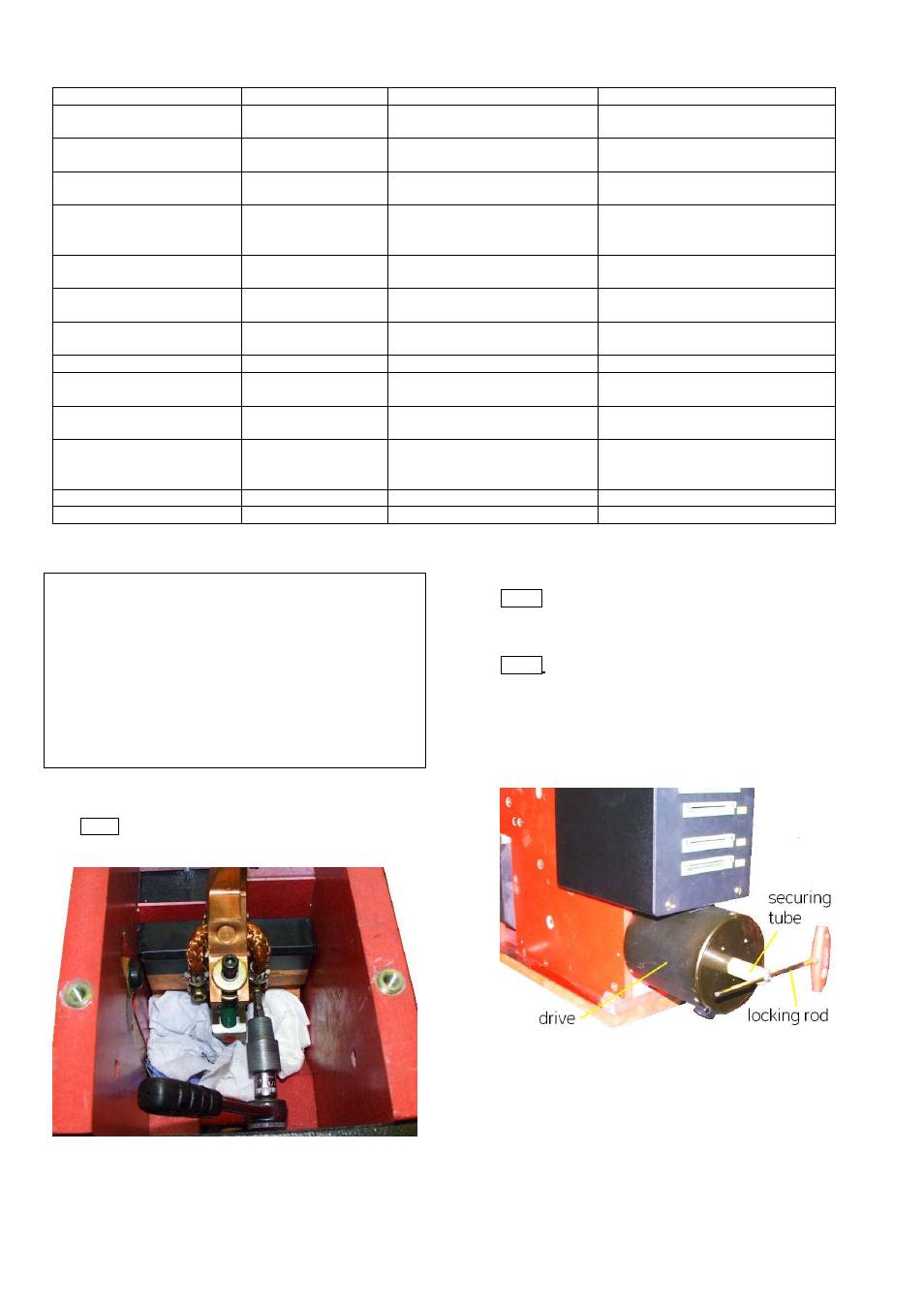
Hint 3 To prevent the risk of injury, it is recommended
to secure the breaker in the closed position with a simple
mechanical interlock device [Fig. b]. A piece of tubing
having ~50 mm [~2 in] length and inner diameter of
minimum 14 mm [0,55 in] works well. The outer diameter
of the locking rod shall be less 8 mm [0,3 in]. GE does not
offer this locking device.
Fig. b Securing closing drive against opening