7 zero voltage release control circuit, Fig. 28 uvr control circuit, 36/ _ _ _ x – GE Industrial Solutions GERAPID 2607, 4207, 6007, 8007 with arc chutes 1X2, 1X4, 2X2, 2X3, 2X4 User Manual
Page 24: X14: uvr pcb
24
Design and specifications are subject to change without notice
S47183e rev.03 2010-06-07
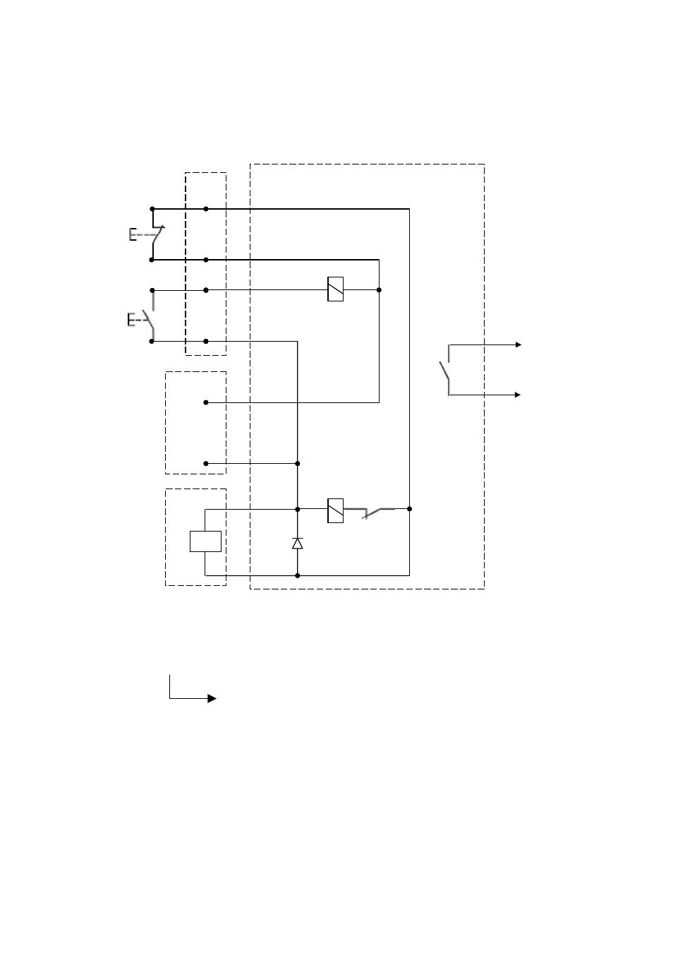
4.3.7 Zero voltage release control circuit
• The closing STOP signal is provided for resetting K2 on the SU-control circuit. It effects with priority in switching
OFF (by ST or UVR) before switching ON. Once switching ON and OFF signals are simultaneous, switching OFF
command will stay longer than switching ON. It means, that OFF command is master command.
• -S2 (-X2 :6/:7) is NO contact, utilized for indirect releasing of the UVR by relay -K2
• -S2 (-X2 :8/:9) is NC contact utilized for direct releasing of the UVR. If it’s not used, please short this connection
permanently.
Fig. 28 UVR control circuit
Key position - 5
Key number - 00: Without shunt trip or zero voltage release.
Key number - 20: With zero voltage release.
36/ _ _ _ X _ _ _
-K2
-K1
-K2
-X14: UVR PCB
[ 1 ]
[ 2 ]
[ 3 ]
[ 4 ]
[ 5 ]
[ 6 ]
[ 7 ]
[ 8 ]
[ 9 ]
[ 10 ]
-X10/11
[ 7 ](-)
DC 24 V
[ 9 ] (+)
-S2
-X2
[ 9 ]
[ 8 ]
[ 7 ]
[ 6 ]
-S3
UVR coil
U<
Closing
STOP relay
-K1