9 auxiliary switch (code 9), Fig. 12 auxiliary contacts layout in control box, 10 indicators – GE Industrial Solutions GERAPID 2607, 4207, 6007, 8007 with arc chutes 1X2, 1X4, 2X2, 2X3, 2X4 User Manual
Page 10: Fig. 13 position indicator, Fig. 14 oct trip target, Fig. 15 arc chute indicator, 11 solenoid closing drive (code 3), Fig. 16 solenoid closing drive and control box
10
Design and specifications are subject to change without notice
S47183e rev.03 2010-06-07
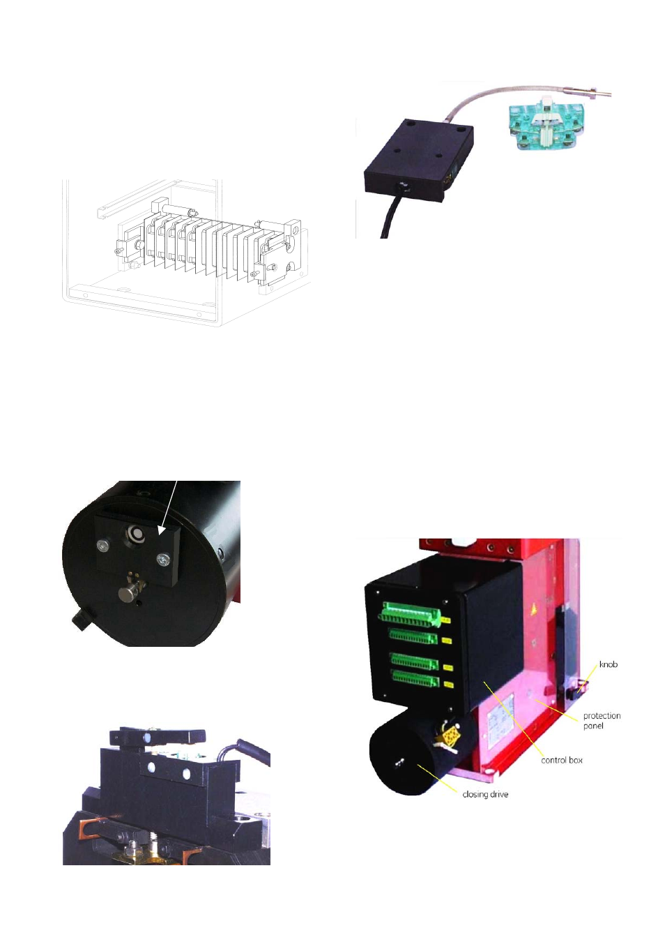
3.2.9 Auxiliary switch (Code 9)
•
Standard breaker can be equipped with 3, 5 or 10
isolated, form C, invertible auxiliary contacts (1 NO/NC
each). The movable main arm activates the contacts.
•
The contacts are wired to 15-pin control terminals: -X4
and -X5, with 5 switches to each terminal [Fig. 21].
•
Conventional thermal current Ith=10
A. Maximum
electrical ratings for switches are 1 A/230 V for AC15. For
DC13 are 0.5 A/110 V and 0.3 A/220 V.
Fig. 12 Auxiliary contacts layout in control box
3.2.10 Indicators
Optionally, the circuit breaker can be equipped with
following indicators:
•
POSITION INDICATOR (Code 14) - mounted at the front of
the closing drive. Mechanically switched by means of
drive’s rod. Indicates position of the main contacts.
“O” – means contacts are open
“I” – means contacts are closed
Fig. 13 Position indicator
•
OC TRIP TARGET (Code 10) – a potential free, NO contact
mounted at the top of the OCT [Fig. 14]. Provides a signal
when OCT trips.
Fig. 14 OCT trip target
•
ARC CHUTE INDICATOR (Code 17) – a potential free, NO
contact mounted on the sidewall. Locks electrically the
closing drive when arc chute is not installed on [Fig. 15].
Fig. 15 Arc chute indicator
3.2.11 Solenoid closing drive (Code 3)
•
A high power solenoid is used to perform fast closing
operation. This drive is mounted at the front of the
breaker and is encased in a grounded casing [Fig. 16].
•
Closing drive is supplied independently from other
controls (-X2 :1/:2), directly from external power source.
Voltage level must be defined at order placement. Rated
power, depends on breaker type, but is between 1.8 kW
and 2.6 kW.
•
CLOSING command is enable by external potential free
contact at (-X2 :4/:5). Signal duration shall be ~300 ms.
•
The closing drive system always includes a self-interrupt
control circuit (SU PCB). This circuit enables short
activation with a time of ~150 ms. SU switches power to
the solenoid and automatically disconnects it after
~400 ms.
•
The SU unit also prevents repeated drive closing, due to
an existing and continuous short circuit conditions and
provides an “anti-pumping” safety feature.
Fig. 16 Solenoid closing drive and control box
•
After closing attempt, the switch-in mechanism is
electrically blocked for approximately 8 sec. Lock time
increases to 14 sec, if internal C-bank (NEKO) is present.
This prevents premature closing following a short circuit.