GE Industrial Solutions AF-300 P11 User Manual
Page 57
5-4
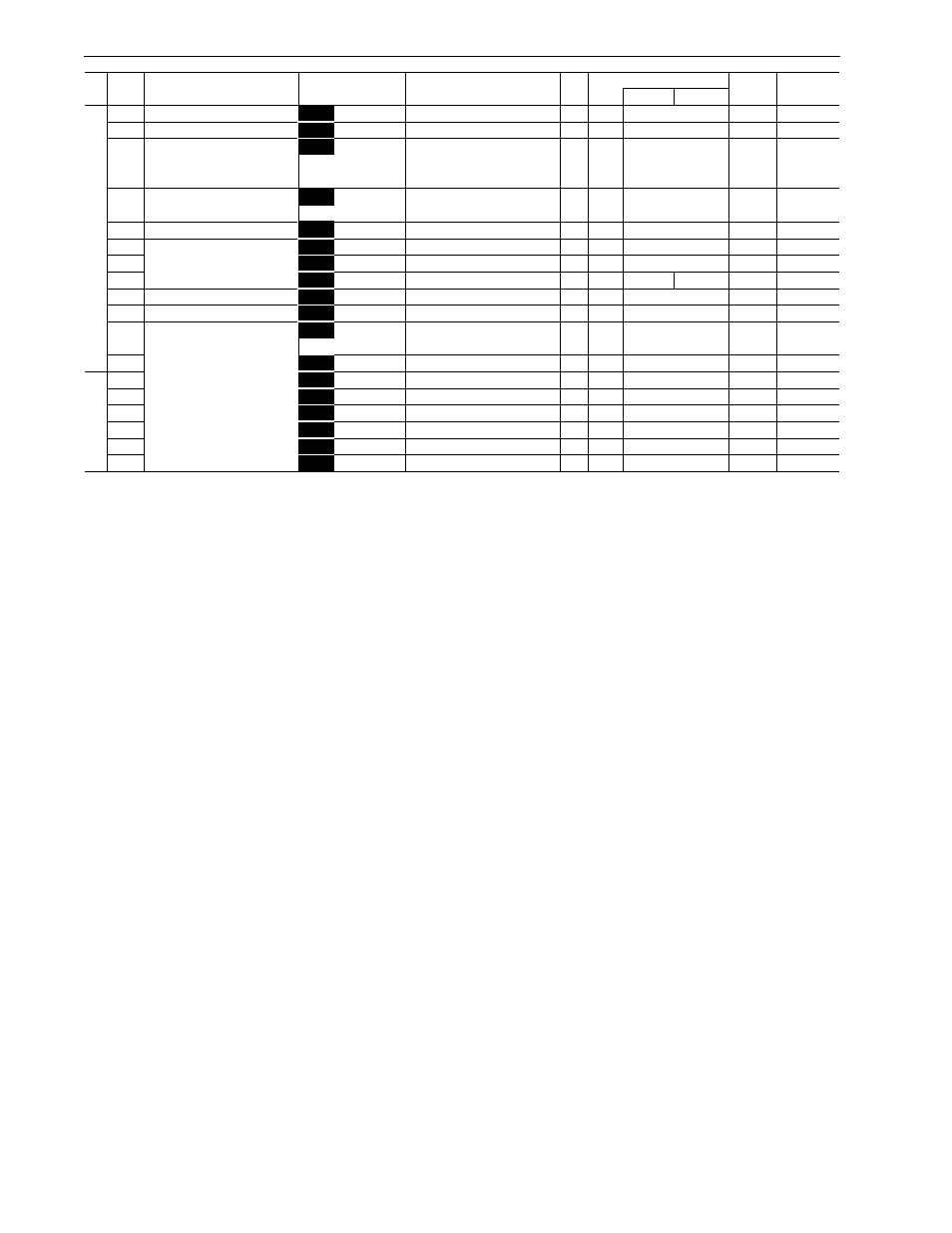
A: Alternative Motor Parameters
Pg.
Func.
Factory Setting
Data
Change
No.
Setting Range
Unit
Min.
30 HP
40 HP
Format
During op
A01
Maximum frequency 2
A01
MAX Hz-2
50 to 120 Hz
Hz
1
60
1
N
A02
Base frequency 2
A02
BASE Hz-2
25 to 120 Hz
Hz
1
60
1
N
A03
Rated voltage 2
A03
RATED V-2
0
V
1
230V class: 230
1
(at Base frequency 2 )
230V class:
80 to 240V
460V class: 460
460V class:
320 to 480V
A04
Maximum voltage 2
A04
MAX V-2
230V class:
80 to 240V
V
1
230V class: 230
1
N
460V class:
320 to 480V
460V class: 460
A05
Torque boost 2
A05
TRQ BOOST2
0.0, 0.1 to 20.0
-
-
2.0
3
Y
A06
Electronic
(select)
A06
ELCTRN OL2
0, 1, 2
-
-
1
1
Y
A07
thermal 2
(level)
A07
OL LEVEL2
20% to 135% if INV rated current
A
0.01
motor rated current
19
Y
A08
(thermal time constant)
A08
TIME CNST2
0.5 to 75.0 min
min
0.1
5.0
10.0
3
Y
A09
Torque vector control 2
A09
TRQVECTOR2
0, 1
-
-
0
1
N
A10
Number of motor 2 poles
A10
M2 POLES
2 to 14 poles
pole
2
4
9
N
A11
Motor 2
(capacity)
A11
M2-CAP
Up to 30 HP: 0.01 to 60 HP
HP
0.01
motor capacity
5
40 HP and above: 0.01 to 600 HP
A12
(rated current)
A12
M2-Ir
0.00 to 2000 A
A
0.01
motor rated current
19
N
A13
(tuning)
A13
M2 TUN1
0, 1, 2
-
-
0
21
N
A14
(on-line tuning)
A14
M2 TUN2
0, 1
-
-
0
1
N
A15
(no-load current)
A15
M2-Io
0.00 to 2000 A
A
0.01
standard rated value
19
N
A16
(%R1 setting)
A16
M2-%R1
0.00 to 50.00%
%
0.01
standard rated value
5
Y
A17
(%X setting)
A17
M2-%X
0.00 to 50.00%
%
0.01
standard rated value
5
Y
A18
(slip compensation control 2)
A18
SLIP COMP2
0.00 to 15.00 Hz
Hz
0.01
0.00
5
Y
N
N
5-45
Name
LCD Display
5-44