GE Industrial Solutions AF-300 P11 User Manual
Page 105
7-4
Data subject to change without notice 7/07. © 2007 GE Drives
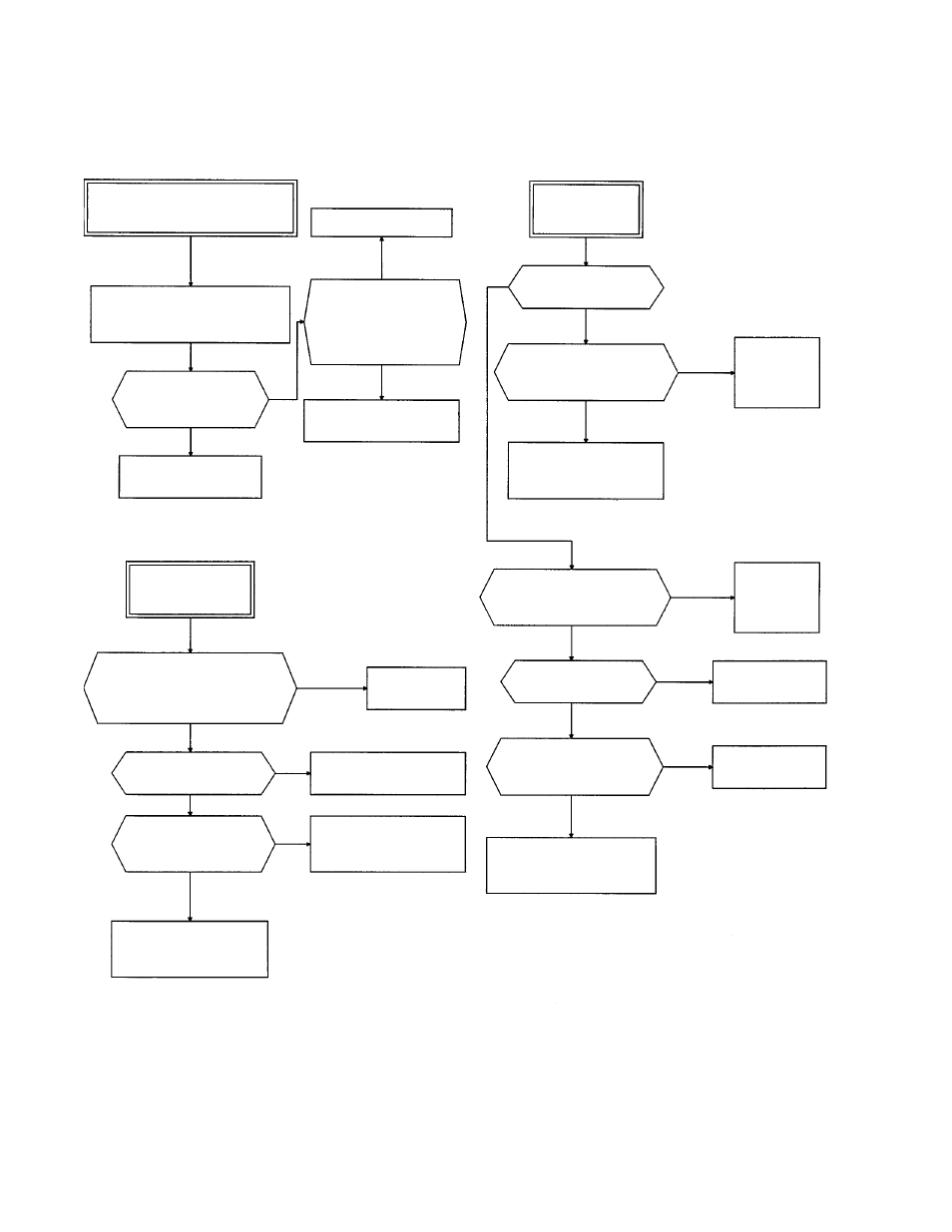
(9) Memory error Er1,
Keypad panel communication error Er2,
CPU error Er3
(10) Output wiring error
(11) Input Phase/Loss
Remedy faulty parts.
Er1, 2, 3 indicated. Abnormal
display or indication goes out.
Are there loose screws on
the terminal block?
Turn the power off then on
again after the CHARGE lamp
(CRG) goes off.
Is data displayed on the
LED monitor correctly?
Drive is normal.
Continue operation.
Are the connectors, plugs,
and ICs inserted correctly?
Is there noise generating
source nearby?
Drive may be faulty.
Contact GE Drive.
Output wiring error
Er7
Did the error occur
during tuning?
Are the braking unit and
braking resistor connected
incorrectly?
Faulty drive or error due
to noise, etc.
Contact GE Drive.
Connect
correctly or
replace the
cable.
Input phase loss
Lin
Are all main circuit power supply
terminals L1/R, L2/S and L3/T
connected to the power supply?
Is the U, V, W terminal wiring not
connected or is there an open
circuit?
The keypad panel
connector is loose.
Connect all three
phases.
Connect
correctly or
replace the
cable.
Secure the
connector.
Disable the
connection.
Is connection between
control terminals FWD,
REV - CM enabled?
Tighten the screws on
the terminal block.
Faulty drive or error
due to noise, etc.
Contact GE Drive.
Is there a significant
imbalance voltage
between phases?
Faulty drive or error
due to noise, etc.
Contact GE Drive.
Faulty drive or error
due to noise, etc.
Contact GE Drive.
YES
YES
NO
NO
NO
NO
YES
YES
YES
YES
YES
NO
NO
NO
YES
YES
YES
NO
NO
NO