GE Industrial Solutions AF-300 P11 User Manual
Page 30
2-13
Data subject to change without notice 7/07. © 2007 GE Drives
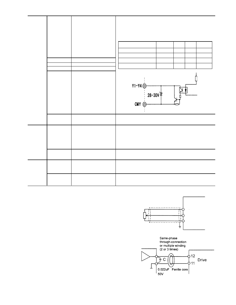
(1) Analog input terminals (13, 12, C1, and 11)
1.
These terminals receive low level analog signals that
may be affected by external noise. The cables must
be as short as possible (20 meters or less), must be
shielded, and the shields must be grounded. If the
cables are affected by external induction noise, the
shielding effect may be improved by connecting the
shield to terminal [11].
2.
If contacts must be connected to these circuits, twin
(bifurcated) contacts for handling low level signals
must be used. A contact must not be connected to
terminal [11].
3.
If an external analog signal output device is con-
nected to these terminals, it may malfunction as a
result of drive noise. To prevent malfunction, connect
a ferrite core or capacitor to the external analog
signal output device.
Item
min. typ.
max.
Operating voltage
ON
–
1V
2V
OFF
–
24V
27V
Maximum load current
ON
–
–
50 mA
Leakage current
OFF
–
–
0.1 mA
Fig. 2-3-10 Example of Noise Prevention
VR
1k to
5K ohms
Drive
13
12
11
Shielded wires
Fig. 2-3-9
Transistor
Y1
Transistor output 1
A running signal, frequency equivalence signal, overload early
warning output signal, and other signals from the drive are output
(as transistor output) to arbitrary ports. For details, see "Setting the
Terminal Functions E20 to E23" in Section 5.2 Function Explanation.
*
Y2
Transistor output 2
Y3
Transistor output 3
Y4
Transistor output 4
CMY
Transistor output common
Common terminal for transistor output signals. This terminal is
insulated from terminals (CM) and [11].
Relay output
30A,30B,30C
Alarm outputs for any fault.
If the drive is stopped by an alarm (protective function), the alarm
signal is output from the relay contact output terminal (1SPDT).
Contact rating: 250 VAC, 0.3A,cosØ = 0.3, 48 VDC, 0.5A for CE
Marking
An excitation mode (excitation at alarm occurrence or at normal
operation) can be selected.
Y5A,Y5C
Multi-purpose signal
These signals can be output similar to the Y1 to Y4 signals above.
The contact rating is the same as that of the alarm output above.
Communic-
DX+,DX–
RTU communication
Input / output signal terminals for RTU communication input / output
ation
Up to 31 inverters can be connected using the daisy chain method.
SD
Communication cable
Terminal for connecting the cable shield. The terminal is electrically
shield connection terminal
floating.-