Wiring connection – GE Industrial Solutions LP33 Series 80 & 100 Installation Guide User Manual
Page 46
Modifications reserved
Page 46/47
OPM_LPS_3UI_80K_M10_1US_V010.doc
Installation Guide LP33 Series 80 & 100 UL S1
Wiring connection
LP
S33U_
080-
100_
UP
S+
EP
O X
A_03
XA
FTM3
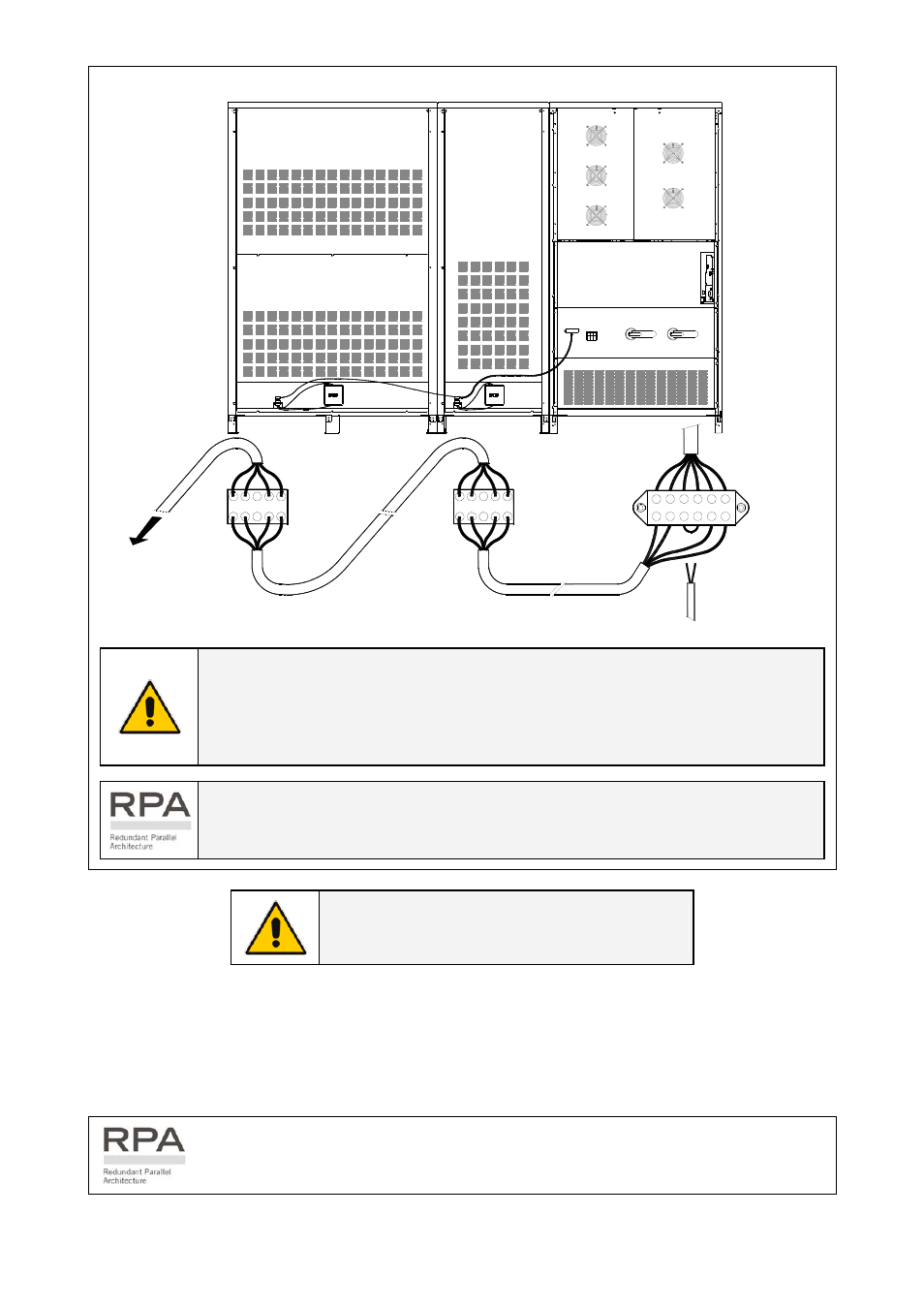
UPS cabinet
Battery cabinet
26"/650mm
FTM3
Battery cabinet
48"/1215mm
1 2 3 4 5 6
1 2 3 4 5 6
Customer EPO connection
UPS internal
connection
Max. rating XA:
2.5mm² / AWG 12
1 2 3 4 5
3
4
XB
XB
1 2 3 4 5
XB -
Female
Max. rating XB:
2.5mm² / AWG 12
Cable 4x
Cable 4x
XB - Female
XB - Male
XB - Female
XB - Male
XB -
Female
Max. rating XB:
2.5mm² / AWG 12
XA
(before to connect
remove the bridge XA - 3/4)
Eventually next
battery cabinet
b
c
d
a
b
c
d
a
Fig. 5-1 Terminals XA and connector XB female – Wiring connection
NOTE !
To enable this function, remove Jumper JP5 on the P1 – Control board and
check the cable connection on the terminal X7 / 1, 2 (see Fig. 4.3-1 / Chapter 4.3).
In case of the Customer Interface, remove the Jumper JP3 and the cable on the
terminal X2 / 1, 2 (see Fig. 4.4-2 / Chapter 4.4).
In a parallel system a separate NC (Normally Closed) contact must be connected
individually to each unit.
NOTE !
This procedure could imply a Load shutdown.
When the EPO has been activated, the system must be restored as follows:
•
Press the push-button EPO (contact on XA / 3, 4 is closed again).
•
Press the key “O” (Inverter OFF – see Section 6.2 of Operating Manual) on the control panel.
•
Press the key “I” (Inverter ON – see Section 6.2 Operating Manual) on the control panel.
In case of a Parallel System press the key “O” (Inverter OFF) on the control panel of
each unit connected on the parallel bus and having its output switch Q1 closed.