4 rpa system - control bus connection, 2 - remove the front panel “ b – GE Industrial Solutions LP33 Series 80 & 100 Installation Guide User Manual
Page 35
Modifications reserved
Page 35/47
OPM_LPS_3UI_80K_M10_1US_V010.doc
Installation Guide LP33 Series 80 & 100 UL S1
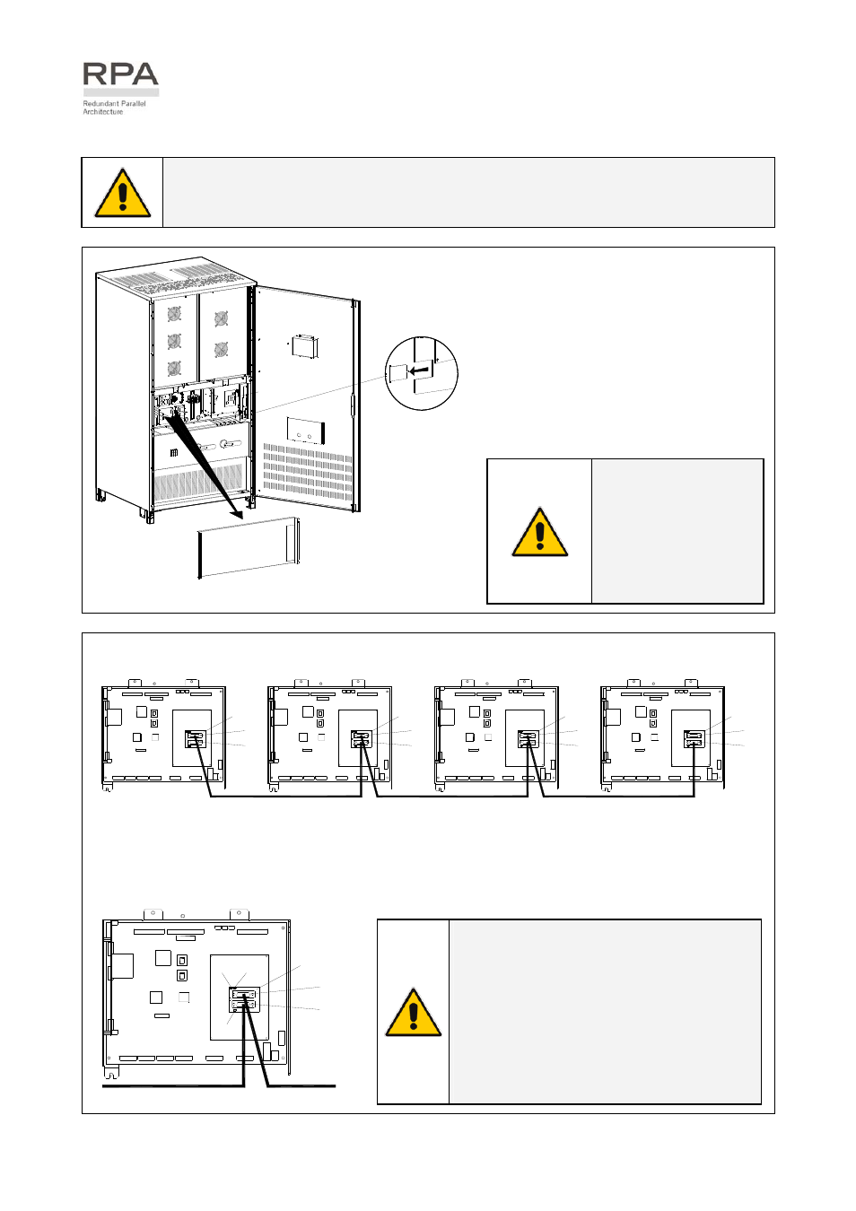
3.9.4 RPA system - Control bus connection
WARNING !
This operation must be performed by TRAINED PERSONNEL ONLY before the initial
start-up (ensure that the UPS installation is completely powered down).
Access to the RPA board
1 - Open the front door “A” of the UPS
cabinet.
2 - Remove the front panel “B”.
3 - Remove with appropriate tool the
metallic window “C” from the metal
screen “D”.
LPS33U_0
80-100_RP
A connect
ion_01
Q2
I ON
0 O
FF
I ON
0 O
FF
F11-12-13
C
P13
B
A
D
Fig. 3.9.4-1 Access to the RPA board
NOTE !
Put in place the front
screen “A” paying
attention to not
damaging the control
bus cables.
LP
S
33U
_030-040_R
P
A
connec
tion_G
E
_02
J4
J3
LP 33 Series
1
P1
P13
P34
P1
J3
P13
J4
P34
LP 33 Series
2
J3
P1
P13
J4
P34
LP 33 Series
3
P34
J4
J3
P1
P13
LP 33 Series
4
Fig. 3.9.4-2 Bus connection RPA parallel system
Bus connection RPA parallel system
Connect the control bus cable between the parallel units as indicated in the diagram Fig. 3.9.4-2.
Provide that the connectors J3 and J4 are properly fixed with the included screws.
NOTE !
The jumper JP1 - JP2 - JP3 must be
removed only on the intermediate units,
where the connectors J3 and J4 are both
inserted.
Do not insert or remove J3 and J4 from the
board “P16 - Connector adapter RPA”
when the parallel system is operating.
P1
J3
P13
J4
P34
LP
S
33
U
_0
30
-0
40
_R
P
A
c
on
ne
ct
ion
_0
3
JP1
JP2
JP3
Fig. 3.9.4-3 Connection to Board P16