2 dual input utility (option) – GE Industrial Solutions LP33 Series 80 & 100 Installation Guide User Manual
Page 30
Modifications reserved
Page 30/47
OPM_LPS_3UI_80K_M10_1US_V010.doc
Installation Guide LP33 Series 80 & 100 UL S1
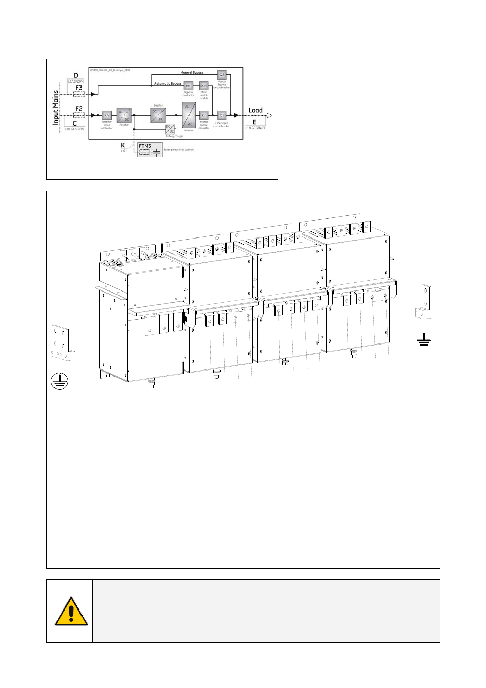
3.9.2 Dual input utility (option)
Fig. 3.9.2-1 Dual Input Utility (option)
Dual input utility
On request, the UPS can be delivered for
Dual Input Utility.
Two independent lines (F2 and F3)
supply separately the rectifier and the
Bypass inputs
With this configuration, when the
rectifier-input fuses are opened, the
Automatic Bypass and the Manual
Bypass are supplied by the other line.
LP
S
33U_080
-100
_
C
onnection sepa
rate
_0
1US
L3
L1
L2
N2
X3
Load
X1
Utility 1
X4
Battery
GND
GND
L3
L1
L2
N1
X2
Utility 2
L3
L1
L2
N
-
0 +
Fig. 3.9.2-2 Terminals for Dual Input Utility
X1 Utility 1 - Rectifier Input Utility connection
L1-1 = Rectifier Phase A
L2-1 = Rectifier Phase B
L3-1 = Rectifier Phase C
N1 =
Utility
Neutral
GND = Main Ground
X2 Utility 2 - Bypass Input Utility connection
L1-2 = Bypass Phase A
L2-2 = Bypass Phase B
L3-2 = Bypass Phase C
N =
Utility
Neutral
X3 Load - Output Load connection
L1 = Load
Phase
A
L2 = Load
Phase
B
L3 = Load
Phase
C
N2 =
Load
Neutral GND = Load Ground
Connect wire to the Terminals by using
appropriate tools and appropriate torque.
Torque specification for Input / Output and DC
power connections on Terminals: Section 3.8.1.
Max. rating X1, X2, X3 & X4 terminals:
2 x AWG 4/0 - Use 167°F (75°C) copper wire
NOTE !
For UPS correct operation, the input utility phase rotation must be clock-wise.
Inside the UPS, all neutrals N1 and N2 are connected together.
This UPS is designed to operate in a wye-configured electrical system with a solidly
grounded neutral.